www.HunterFan.com
1.888.830.1326
M0093-01 • 06/17/20 • © 2020 Hunter Fan Company
If you are installing multiple remote-controlled fans
on the same circuit breaker,
you may need to perform a few extra steps to prevent
interference or faulty operation of your remote controls.
Go to www.HunterFan.com/FAQs and click “How do I properly
install multiple remote-controlled fans?” for more information.
Turn the splices upward and push them carefully back through the hanger bracket
into the outlet box. Spread the wires apart, with the grounded wires on one side of
the outlet box and the ungrounded wires on the other side of the outlet box.
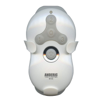
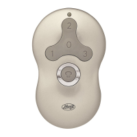
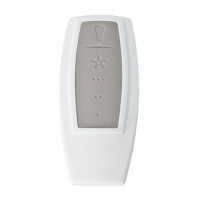
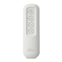
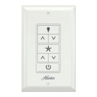
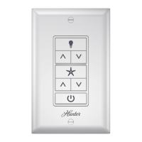
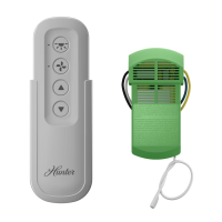
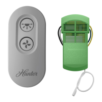
Original Accessory
Control and Canopy
Models 99179, 99180,
99181, 99173
Note: A 12 inch or longer
downrod (sold separately) is
required for the installation
of the Original Control and
Canopy Accessory Kit.
If your fan has not been installed, follow
the TYPE-A ASSEMBLY INSTRUCTIONS.
If your fan is already installed and the
canopy is held by two screws near the
downrod as shown, follow the TYPE-B
ASSEMBLY INSTRUCTIONS.
Canopy
Screw
If your fan is already installed and the
canopy is held by three screws near
the ceiling as shown, follow TYPE-C
ASSEMBLY INSTRUCTIONS.
Canopy
Screw
A
Install the fan according to the fan’s
manual, but do not install the canopy.
Wire the grounding wire according the
fan manual’s instructions. Proceed to
wiring instructions.
Remove the three canopy screws. Lower
the canopy and the canopy insert. With
wiring exposed, it may be helpful to note
existing wire connections or take a digital
photo for reference. Remove the wire
connectors that connect the wires from
the outlet box to the fan. Unhook the fan
from the ceiling.
Reinstall the fan according to the
installation manual included with
the fan, but do not install the
ceiling plate, canopy, or canopy
insert. Rewire the grounding wire
according to the fan manual.
Proceed to wiring instructions.
Remove the two canopy screws.
Canopy
Screw
Remove the two canopy halves. With
wiring exposed, it may be helpful to
note existing wire connections or take a
digital photo for reference. Remove the
wire connectors that connect the wires
from the outlet box to the fan, leaving the
grounding wire connected. Proceed to
wiring instructions.
Remove the downrod by unscrewing the
bottom set screw. Unscrew the downrod.
Remove the canopy and canopy insert.
Reinstall the downrod according to the
fan manual.
Setscrew
Canopy
Canopy
Insert
Downrod
Remove the u-bracket and the ceiling
plate from the ceiling.
Installation
Turn Power
OFF
Before installing the Universal
Remote Control Receiver,
use the pull chains to set the
fan speed to HIGH and the
light to ON. Be sure power is
OFF before proceeding with
installation.
Have the
fan manual
available for
reference.
B B
C CCC
CONNECT WIRES FROM RECEIVER AND FAN TO WIRES FROM OUTLET BOX - Using the orange
wire connectors, connect the black wire (ungrounded) from the ceiling to the black wire from
the receiver. Connect the white wire (grounded) from the ceiling to both the white wire from the
receiver and the white wire from the fan.
AFTER ALL WIRES ARE CONNECTED and secured with wire connectors, re-install the canopy.
F
R
O
M
R
E
C
E
I
V
E
R
black
white white (grounded)
black (ungrounded)
white
F
R
O
M
C
E
I
L
I
N
G
F
R
O
M
F
A
N
Wiring
CONNECT WIRES FROM RECEIVER TO FAN - Using the orange wire connectors, connect the blue wire from the
receiver to the blue wire (or possibly black with white stripe wire) from the fan. Connect the yellow wire from the
receiver to the black wire from the fan.
If you’re uncertain about wire colors or connections, please contact a qualied electrician.
F
R
O
M
R
E
C
E
I
V
E
R
black
blue
yellow
blue
F
R
O
M
F
A
N
To avoid possible electrical shock, before
installing your fan, disconnect the power by
turning off the circuit breakers to the outlet
box associated with the wall switch location.
All wiring must be in accordance with
national and local electrical codes ANSI/NFPA
70. If you are unfamiliar with wiring or in
doubt, consult a qualied electrician.