Step Title
10
42746-01 • 04/26/07 • Hunter® Fan Company
Screw
Boss
Upper Pole
Segment
Upper Pole
Screw
74514-60-247
(x 4)
Hardware Needed:
Switch Housing
Screw
64555-05-247
(x 3)
Hardware Needed:
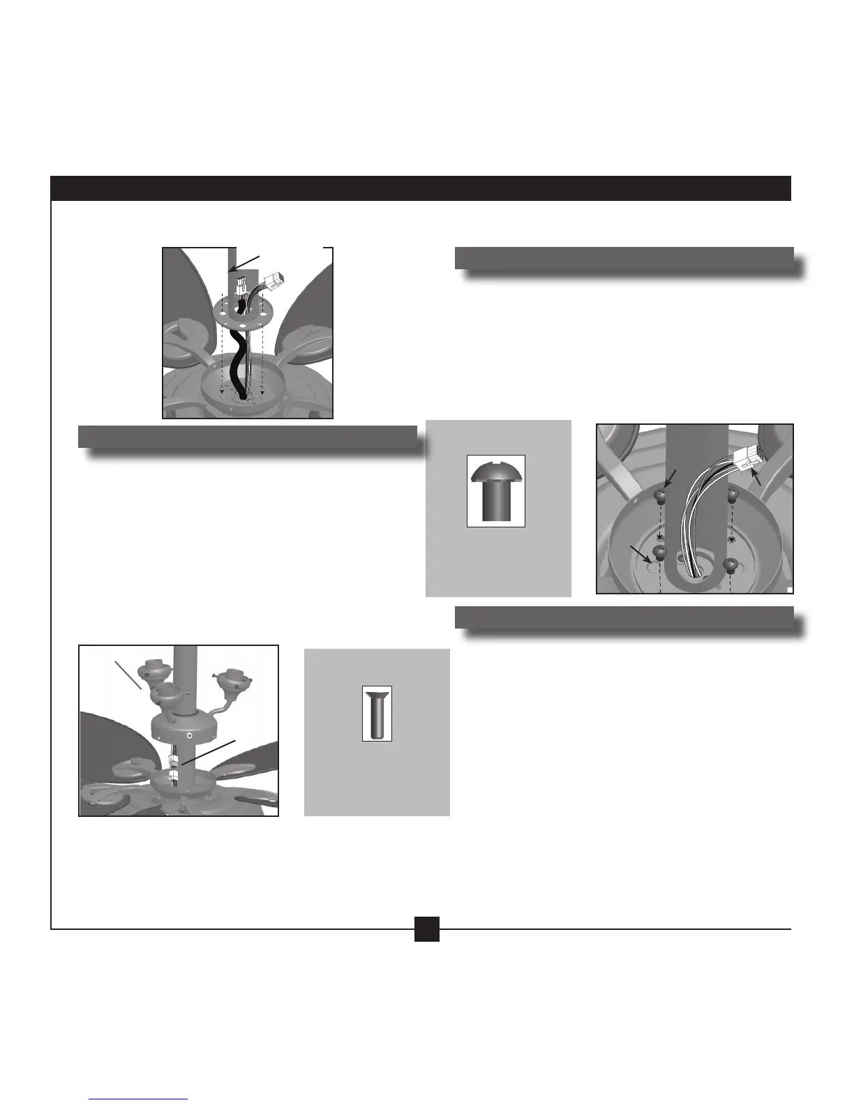
6-1. read the power cord with the 3-pin plug connector
from the fan through the upper pole segment.
6 • Assembling the Light Kit
6-2. Pull the 9-pin plug connector through the side
of the upper pole segment. Align the holes in the
upper pole segment with the bosses in the upper
switch housing. Install four screws to secure the
upper pole segment to the fan.
Step 6-1:
Step 6-2:
6-3. Being careful not to damage the fan finish,
slide the light kit onto the upper pole segment
holding the grommet in place. Connect the 9-pin
plug connector from the fan to the 9-pin plug
connector from the light kit.
6-4. Align the holes in the side of the light kit with the
holes in the upper switch housing and securely
install three switch housing screws.
Steps 6-3 - 6-4:
9-Pin
Plug
Con-
nector
Plug
Connectors
Light Kit
 Loading...