20
41557-01 3/12/2002
®
from the lower switch housing
assembly. See Figure 8d.
Note: Both plug connectors are
polarized and will only fit to-
gether one way. Make sure that
both connectors are properly
aligned before connecting them
together. Incorrect connection
could cause improper operation
and damage to the product.
4. Align the keyhole slots in the up-
per switch housing with the hous-
ing assembly screws installed in
sub-step 2.
5. Turn the lower switch housing
clockwise until the housing as-
sembly screws installed in sub-
steps 1 and 2 are firmly situated
in the narrow end of the keyhole
slots as shown in Figure 9e.
Tighten all four screws firmly.
6. Partially install two of the screws
into the lower switch housing to
mount the light kit.
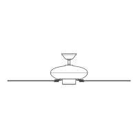
Figure 8d - Attaching Lower Switch
Housing/Light Assembly
CAUTION
Make sure the lower switch
housing/light assembly is se-
curely attached to the switch
housing mounting plate.
Failure to properly attach and
tighten all four housing assem-
bly screws could result in the
switch housing and light
fixture falling.
Figure 8e - Light Assembly
7. Install one Max 100 Watt light
bulb.
8. Align the keyhole slots in the light
kit with the screws installed in the
lower switch housing. Refer to
Figure 8e.
9. Turn the light kit clockwise until
the screws installed are firmly situ-
ated in the narrow end of the
keyhole slots. Securely install the
third screw and tighten all screws.