DC Electric Systems
7.5
You can view the parts of the DC side of the main control
panel here (Fig. 7.3). Notice the battery selector switch
at the top right, when switched on the respective voltage
of the battery is shown above on the digital volt meter.
Indicator lights are built into most switches and alert you
that the selected system is powered.
The distribution panel is outlined in the legends section
of this chapter.
Refer to the “Operations” section of this chapter to view
instructions on how to energize the separate systems on
your boat.
7.2 Systems and Components
There are many systems and components on the DC side
of your boat from emergency and safety to entertainment.
These systems make up the largest part of your electrical
system.
Here we will discuss the electrical parts of those systems
and try and give you a better understanding of the uses
and features of your DC electrical systems and compo-
nents. Since the largest part of your controls are at the
MDP, we will start there and run down the systems and
components as they are listed on the MDP. From there,
we will look at the battery switch panel, and finally, the
helm controls.
7.2.1 DC Main
In order to energize the DC system aboard your boat, you
must turn the breaker marked “DC Main”, on the battery
switch panel, to the “On” position. This supplies power to
the remaining breakers and systems on the distribution
panel.
7.2.2 Water Systems
The water systems are outlined in the Water Systems
chapter in this manual. However, the controls and
monitors for these systems are all powered by the DC
Electrical system.
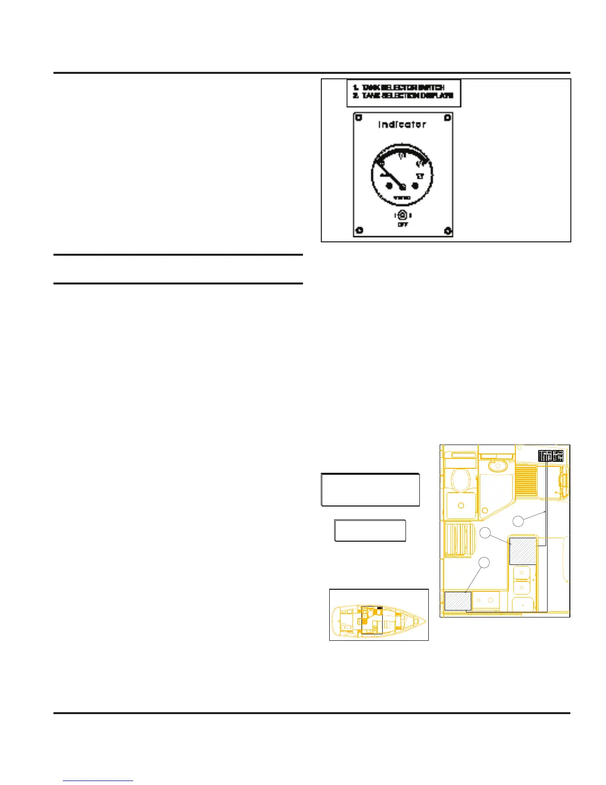
The water tank monitor as shown in Fig. 7.4 allows you
to select the tank to monitor the water level in the respec-
tive tank.
The power switch turns the monitor on, then
select the tank you want to monitor. The gauge
will show the amount remaining in the tank(s).
The water and waste tanks are monitored from the tank
selection panel.The switch in #1 position monitors the
water tank. The waste tank is also monitored from this
location by switching to #2 position and center position is
“OFF” Fig. 7.4.
7.2.3 Refrigerators
The breaker marked “refrigerator”, on the main breaker
panel behind the nav station acess panel, supplies
power to the DC powered refrigerator aboard your boat.
See Fig. 7.5 for the arrangement layout of this system.
Fig.7.4
Fig.7.5
A
B
AREA DEPICTED ABOVE
NOTE: CONSULT PRODUCT MANUAL
FOR OPERATING THE REFRIGERATOR
AND FREEZER UNITS.
A REFRIGERATOR W/BUILT IN
COMPRESSOR
B POWER RUN TO D.C. PANEL
C OPTIONAL FREEZER
**
**
C