The fuel tank fill fitting is located on the stbd. side on the
stern. The fuel tank also has a hull vent fitting. This fitting
is also located on the port side near the fuel fill. You can
see the fill in detail in Fig. 5.2, on page 5.3.
The fuel tank vent serves as a pressure / vacuum release
and a safety overflow. The vent is a thru hull fitting
with a flame arrestor, so it is imperative that you keep
the screens clear and in excellent repair. Replace the
screen immediately if it becomes damaged or displaced.
Periodically check the vent to see that it is not clogged.
The fuel fill and fuel vent hoses, fittings, and connec-
tions should be inspected for leaks and signs of dry rot
or swelling at least once a year. If any of these condi-
tions are present, have an authorized service technician
inspect the fuel system immediately. If a leak is found,
turn off battery switches, disconnect shore power, and
disable any possible source of ignition. Contact your
dealer or Customer Service immediately.
The use of any hose other than the USCG Type A1
or A2 could result in fuel leakage. Leaking fuel is a
fire and explosion hazard. Personal injury or death
could result.
5.2 Fuel Supply Lines and Hoses
If any fuel fill or vent hose's are in need of replacement,
ensure that only USCG Type A1 or A2 are used. The
engine has a fuel supply hose that runs from the pickup
tube in the fuel tank to the fuel water separator (com-
monly referred to as the fuel filter), then from the filter to
the engine. Also, the engine has a fuel return hose that
runs from the engine back to the fuel tank. If your boat
has a generator, the generator will have somewhat the
same setup, with the supply and return hose. The fuel
supply lines or hoses, fitting, and connections should be
inspected often for leaks and signs of wear, dry rot, chaf-
ing, or swelling. A good way to inspect the fuel hoses is
to run your hand along the length of the hose including
the fittings. Leaks will be revealed as wet spots on your
hand. If any evidence of hose deterioration is present,
have a qualified technician replace all the hoses with
USCG Type A1 hoses immediately!
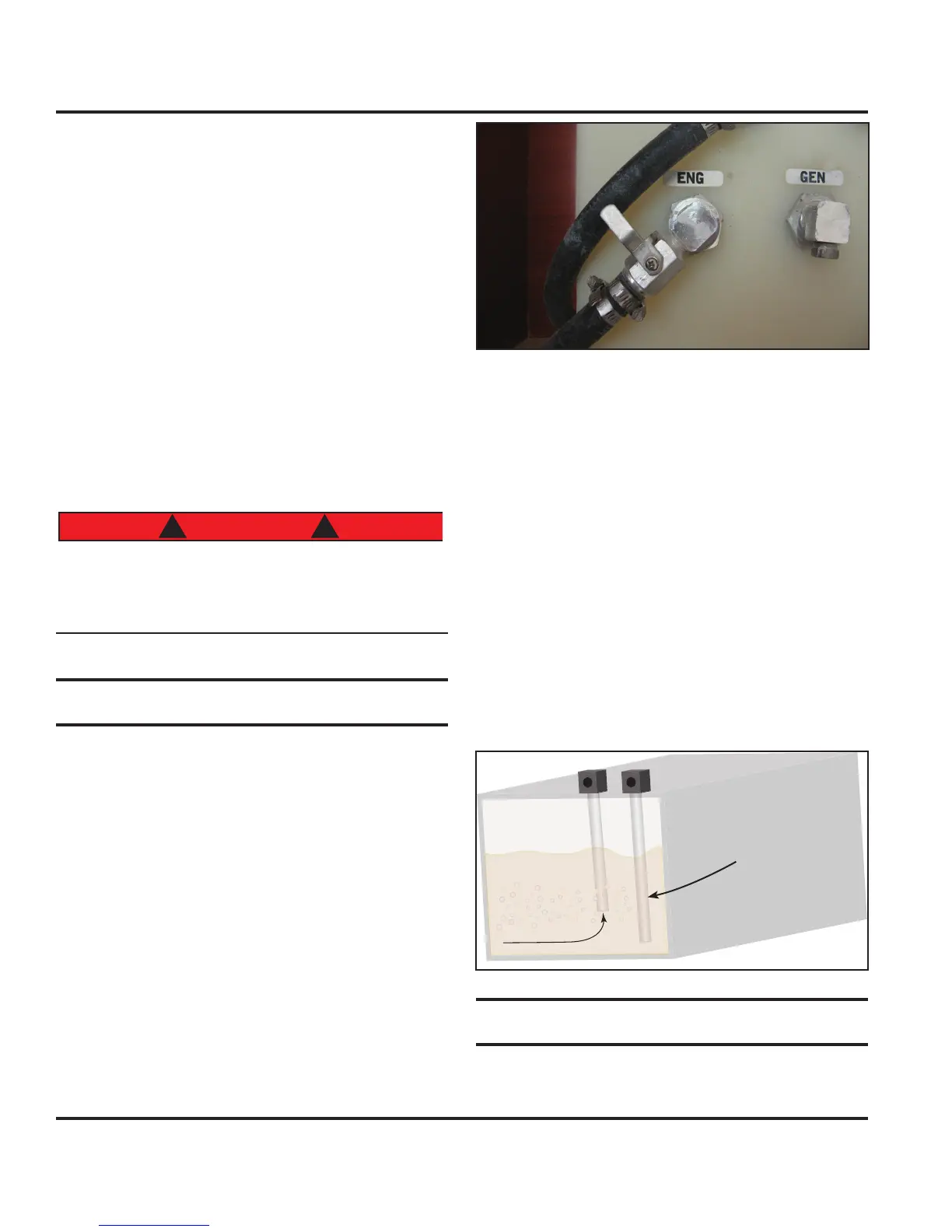
In Fig.5.3 you can see the fuel supply fittings. The photo
inset shows the close-up of the fuel valve. See Fig.5.5
for the function of the fuel valves.
Note: If a leak is found, turn off battery switches, disconnect
shore power, and disable any source of ignition. Do not start
your engines, the generator, or any devices that could cre-
ate a spark. Contact your dealer or our Customer Service
Department immediately! If hoses need to be replaced, make
sure only USCG Type A1 are used.
5.2.1 Generator Fuel Supply Notice
In Fig. 5.4 we demonstrate the layout of your boat's
fuel pick up lines in the fuel tank. See the Mechanical
Arrangement Drawing in the Boating Safety chapter of
this manual for more location information. In the image
you can see the pick up for the generator is located
higher than the engine pickup
This is a safety feature of your boat, to ensure that the
generator never depletes the fuel to the engines.
5.3 Fuel Valves
Your boat has fuel shutoff valves located at the tank in the
supply line route. These valves are used to start or stop
the flow of fuel through the supply lines.
Fig. 5.3
Fig.5.4
Engine pick-up
Fuel Systems
5.4