Do you have a question about the Hunter PC-300 and is the answer not in the manual?
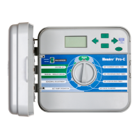
Explains modularity for inventory management and serviceability of the Pro-C controller.
Highlights how modularity simplifies contractor inventory by stocking base units and modules.
Automatically skips shorted stations, aiding in identifying wiring problems without blowing fuses.
Uses MOVs to protect microcircuits from electrical surges and lightning.
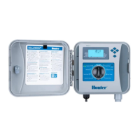
Guides on routing valve wires and connecting AC power for the controller.
Instructions for routing AC power cable and conduit into the outdoor cabinet.
Instructions for routing transformer cable and connecting wires inside the indoor controller.
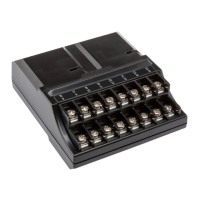
Explains how to install and connect expansion modules (PCM-300, PCM-900) using the Easy-Lock feature.
Guides on connecting a master valve to the P/MV terminal for systems requiring it.
Instructions for connecting a pump start relay, emphasizing placement and electrical considerations.
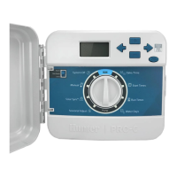
Introduces the controller's programming features like the LCD display and dial design.
Step-by-step guide to setting the controller's current date and time using the dial and buttons.
Instructions on how to set up to four start times per program (A, B, or C).
Guide to setting individual station run times, from 1 minute up to 6 hours.
Explains options for selecting watering days, including specific days, interval, odd, or even days.
Allows global adjustment of run times (10%-150%) based on seasonal weather changes.
Process to reset the controller to factory defaults and erase all programmed data.
A diagnostic procedure to identify wiring problems like shorts.
Addresses issues where the controller display shows no information, checking power wiring.
Troubleshoots general error messages, including electrical noise or wiring harness issues.
Addresses ground faults in the wiring for the pump start or master valve.
Identifies ground faults in station wiring, requiring wire repair or connection checks.
Indicates no AC power is present, requiring checks on transformer installation.
Signifies rain sensor interruption or lack of installation, recommending bypass or sensor check.
Discusses issues with rain sensors, suggesting micro-switch type sensors and proper jumper removal.
Addresses issues where the controller doesn't recognize all installed modules, suggesting power cycle and module checks.
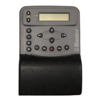
Explains the need for and preparation of the SmartPort wiring harness for SRR connectivity.
Step-by-step guide to installing the wiring harness for the SRR remote control system.
Details key operating specs like address codes, station support, run times, and range.
Lists electrical details for the transmitter and receiver, including frequency and power.
| Brand | Hunter |
|---|---|
| Model | PC-300 |
| Category | Controller |
| Language | English |