Rain-Clik
™
Rain Sensors
Installation Instructions
INTRODUCTION
The Rain-Clik
™
you have just purchased provides a new level of performance,
water savings, and installation convenience never seen before in an economical
rain sensor package.
The Rain-Clik acts as a switch to break the circuit to the solenoid valves of
the irrigation system when it has rained. This allows the timer to advance as
scheduled, but keeps the valves from opening the water flow. Once the Rain-
Clik has dried sufficiently, the switch closes again to allow for normal operation.
The Rain-Clik is supplied with 25 feet of wiring for installation on your controller.
Unlike other rain sensors, you do not need to figure out the setting for rainfall
shutoff. The Rain-Clik is self-adjusting. Your sprinkler system will be shut down
within the first few minutes of any rainfall, yet the total amount of rain received
is registered inside the unit and determines how long your system will stay off.
The Rain/Freeze-Clik includes a freeze sensor that is designed to keep the
system from operating at or below 37°F (3°C). At temperatures above 37°F, it
will close the circuit for normal sprinkler operation. The freeze sensor prevents
ice on landscapes, roadways and walkways.
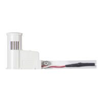
MOUNTING
Standard Mount:
Using the screws provided within the package, mount the Rain-Clik on any
surface where it will be exposed to unobstructed rainfall, but not in the path of
sprinkler spray. The switch
housing portion must be
upright (as pictured), but
the swivel-bracket can
be moved for mounting
on any angles surface.
Loosen the locknut and
screw before swiveling
the bracket, and then re-
tighten.
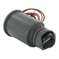
Gutter Mounting (SGM
Sold Separately):
The gutter mount can be
purchased as an optional
accessory for your Rain-
Clik (order p/n SGM). The
SGM allows the Rain-Clik
to be mounted directly
to the side of a gutter. To
install your Rain-Clik on a
gutter, remove the screw,
nut, and standard metal
extension arm supplied
with the Rain-Clik, and
reinstall the screw and
gutter mount. Position the
gutter mount on the edge
of the gutter and twist the
thumbscrew to secure it
in place.
Helpful Hints for
Mounting:
A. When looking for
a suitable location
such as the side of a
building or post, the
closer the Rain-Clik is
to the controller, the
shorter the wire run
will be. This will also
minimize the chance
for wire breaks.
B. Correct placement of the Rain/Freeze-
Clik model is important for accurate
temperature sensing. The best location
would be out of direct sunlight (Fig A).
C. As described in the “Operation” section
of this manual, “reset rate” refers to the
amount of time it takes the Rain-Clik
to dry out sufficiently for the sprinkler
system to be allowed to come back on.
The mounting location will affect this rate
and should be taken into consideration
should extreme conditions exist. For example, mounting the Rain-Clik on a
very sunny, southern end of a building may cause the Rain-Clik to dry out
sooner than desired. Similarly, mounting on the northern end of a building
with constant shade may keep the Rain-Clik from drying soon enough.
Once the Rain-Clik is mounted, run the wire to the controller, and fasten it
every few feet with wire clips or staples for best results. Be careful not to cut
through the wire insulation with fastening hardware or chaff the insulation when
routing wire through or around metal materials (i.e. gutter, siding, etc.). If an
extension to the wire provided is needed, use the following table to determine
the minimum wire gauge needed:
WIRING TO YOUR IRRIGATION SYSTEM
Important: The Rain-Clik is sold and designed for hook up to 24 Volt irrigation
controllers only.
WARNING! This unit is
designed to be installed
in conjunction with
24VAC circuits only.
Do not use with 110 or
220VAC circuits.
Wiring to the Hunter SRC
The Rain-Clik connects
directly to the SRC. This
allows you to easily override
the sensor by using the RUN
(BYPASS SENSOR) position
on the dial.
1. Route the wires from the
Rain-Clik up through the
same opening used for
valve wiring.
2. Connect one wire to the RS
terminal and other to the C terminal (See Figure 1).
3. Connect the valve common to the RS terminal.
Wiring to the Hunter ICC, Pro-C, or EC Controllers
The Rain-Clik connects directly to the ICC or Pro-C. This allows you to easily
override the sensor by using the Sensor switch on the front panel.
1. Remove the jumper from the two “SEN” terminals.
2. Route the wires from the rain sensor up through the same conduit opening
used for valve wiring.
3. Connect one wire to the terminal labeled “SEN” and the other wire to the
other “SEN” terminal (See Figure 2).
Other Controllers
The two most common situations are shown below.
A. 24 Volt Solenoid Valves Only (No booster pump) (See Figure 3).
With the two wires from the Rain-Clik at the controller, locate the “common
ground” wire of the solenoid valves. If it is connected to the common terminal
on the controller, disconnect it. Attach one wire of the Rain-Clik to the
“common” terminal (usually marked “C”) on the controller. Attach the other
wire of the Rain-Clik to the common wire leading to the valves. Note: The
common wire to the valves does not have to be interrupted at the controller.
The Rain-Clik may be wired anywhere along the common wire line.
B. 24 Volt Solenoid Valves with Booster Pump (See Figure 4).
Locate the common wire to the solenoid valves and the common wire leading
to the coil of the relay that starts the pump. If these two wires are connected
to the “common” terminal on the controller, disconnect both of them.
Standard Mount
1 2 3 4
Rain-Clik
TM
Hunter SRC
C
Figure 1
RS
Connect Common to
this Te
rminal when
using Rain Sensor
Connect Rain
Sensor Wires to
These Two Terminals
Solenoid
Va
lves
If the extension needed is: 25-50 ft. 50-100 ft. 100 ft or more
use: 20 AWG 18 AWG 16 AWG
Gutter Mount (Optional)
Shade
Rain/Freeze-Clik
Figure A
http://waterheatertimer.org/How-to-wire-Intermatic-sprinkler-timers.html