AC AC RRSCMV 123456
White
Blue
Red
7
SRC Controller SmartPort
®
Installation
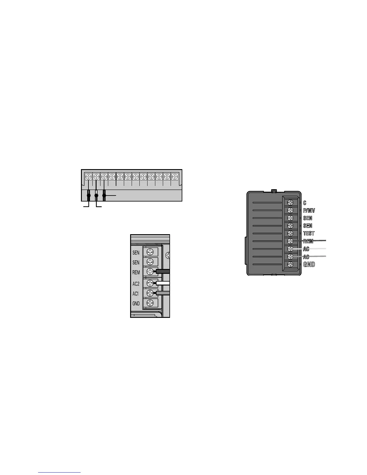
Access the terminal strip area and attach the red wire
to the left AC screw slot, attach the white wire to the
next AC screw
slot and attach
the blue wire
to the screw
slot marked
“R”.
Pro-C Controller SmartPort
®
Installation
Access the terminal strip area
on the main module and attach
the red wire to the bottom most
AC screw slot, attach the white
wire to the upper AC screw slot
and attach the blue wire to the
screw slot marked “REM”.
ICC Controller SmartPort
®
Installation
Access the terminal strip area on the power module
and attach the red wire to the bottom most AC screw
slot, attach the white wire to the upper AC screw slot
and attach the blue wire to the screw slot marked
“REM”.
WiRinG THe sMaRTPoRT
®
To HunTeR ConTRolleRs .........