7
8
Fan style may vary.
Note:
Fan style may vary.
Note:
Ceiling Bracket Downrod Hanging Fan Wiring Canopy Blades Light ControlGlass
ON
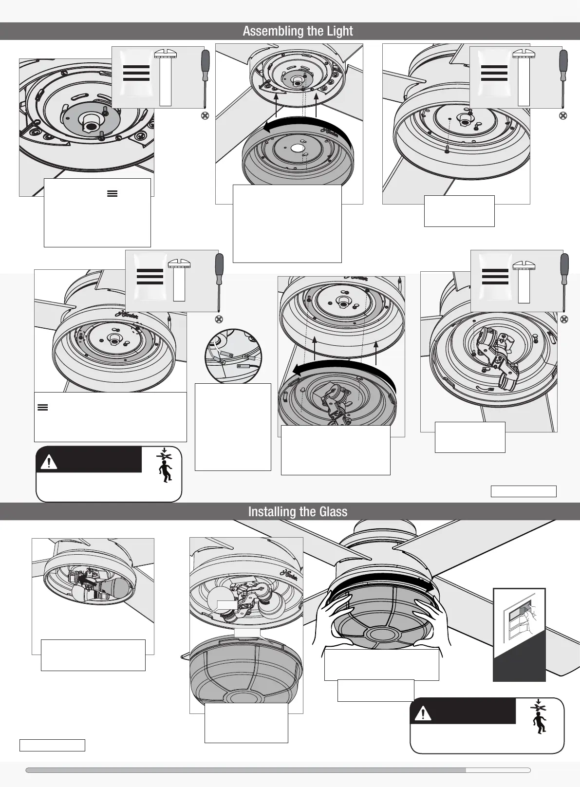
Turn Power
Lift the glass assembly
and align the notches in
the glass assembly with
the tabs in the light kit.
Attach the glass assembly by lifting
and turning clockwise one third of a
full turn of the glass until it stops.
Notch
Tab
GLASS FALL HAZARD
To prevent SERIOUS INJURY or DEATH, make
sure that glass is properly secured.
Partially install two light kit
screws, found in the hardware
bag, through the upper switch
housing gasket halfway into the
motor housing as shown. It does
not matter which two screw holes
you choose.
Partially install two light kit screws, found in the
hardware bag, through the light kit gasket
halfway into the upper switch housing as shown.
It does not matter which two screw holes you
choose.
FAN FALL HAZARD
Make sure all screws are tight to secure
the light xture.
2 of 3
2 of 3
1 of 3
Light Kit
Screw
bag
bag bag
bag
Lift the upper switch housing and
align the keyhole slots in the top of
the upper switch housing with the
partially installed light kit screws.
Feed the wires through the center
hole of the upper switch housing,
then wrap keyhole slots around the
screws and twist counterclockwise
Align the keyhole slots in the top
of the light kit with the partially
installed light kit screws. Wrap the
keyhole slots around the screws
and twist counterclockwise
Install the third screw.
Tighten all three
screws securely.
Install the third screw.
Tighten all three
screws securely.
Connect the wires from
the light kit to the wires
from the fan. Connect
the white wire to the
white wire. Connect the
blue wire to the black
wire. Tuck the excess
wiring above the light
kit.
NOTE: Check to ensure
proper engagement.
Install the included bulbs into the
sockets. When necessary, replace
with bulbs of same wattage.
Short Light
Kit Screw
Short Light
Kit Screw
1 of 3
Light Kit
Screw
 Loading...