4 •
••
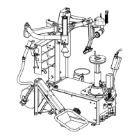
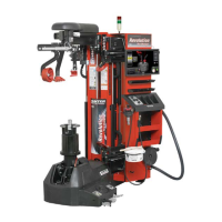
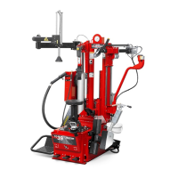
• Getting Started TC39 Series Changer Operation Instructions
1 128-284-2 DECAL-SAFETY INSTRUCTIONS
2 128-323-2 DECAL-EYE PROTECTION
3 128-1213-2 DECAL-TCA TPMS SENSOR
4 128-286-2 DECAL-DANGER AIR BLAST
5 128-1149-2 DECAL-WARNING AIR BLAST
6 128-489-2 DECAL-MOUNTING ARM INCLINATION
7 128-435-2 DECAL-REMOVE CLIP-ON WEIGHTS
8 128-287-2 DECAL-WARNING INFLATION
9 128-285-2 DECAL-WARNING PRESSURE LIMITATIONS
10 128-504-2 DECAL-DO NOT BREAK BEAD WITH AIR
PRESSURE IN TIRE
11 128-505-2 DECAL-KEEP ARMS AND LEGS CLEAR OF BEAD
BREAKER
12 RP6-3691 DECAL-INFLATION
13 RP6-710211210 DECAL-ROTATION DIRECTION
14 RP6-99990758 DECAL-ELECTRICITY DANGER
15 RP6-4244 DECAL-ROTATING PARTS DANGER INDICATING
16 128-1241-2 DECAL-KEEP CLEAR
17 RP6-999916311 DECAL-RUBBISH SKIP
18 RP6-999915200 SERIAL NUMBER PLATE
19 RP6-1594 DECAL-INSTALLATION DATE
20 128-1748-2 TC LOGO PLATE
21 128-1750-2 TC39 PLATE
22 RP6-999923160 DECAL-WARNING PROP 65
23
24
999923960
RP6-4221
BEAD PRESS ARM PLUS PLATE
GROUNDING PLATE
25 RP6-999923950 DECAL-INDENT
26 RP6-999923990 DECAL-ROLLER
27 RP6-999923940 DECAL-TOOL HEAD
Electrical
The TC is manufactured to operate at a specific voltage and amperage rating.
Make sure that the appropriate electrical supply circuit is of the same voltage and
amperage ratings as marked on the TC.
WARNING: DO NOT ALTER THE ELECTRICAL PLUG. Plugging the
electrical plug into an unsuitable supply circuit will
damage the equipment.
Make sure that the electrical supply circuit and the appropriate receptacle is installed
with proper grounding.
To prevent the possibility of electrical shock injury or damage to the equipment when
servicing the TC, power must be disconnected by removing the power cord from the
electrical power outlet.
 Loading...