44092-01 • 12/15/10 • Hunter Fan Company
5
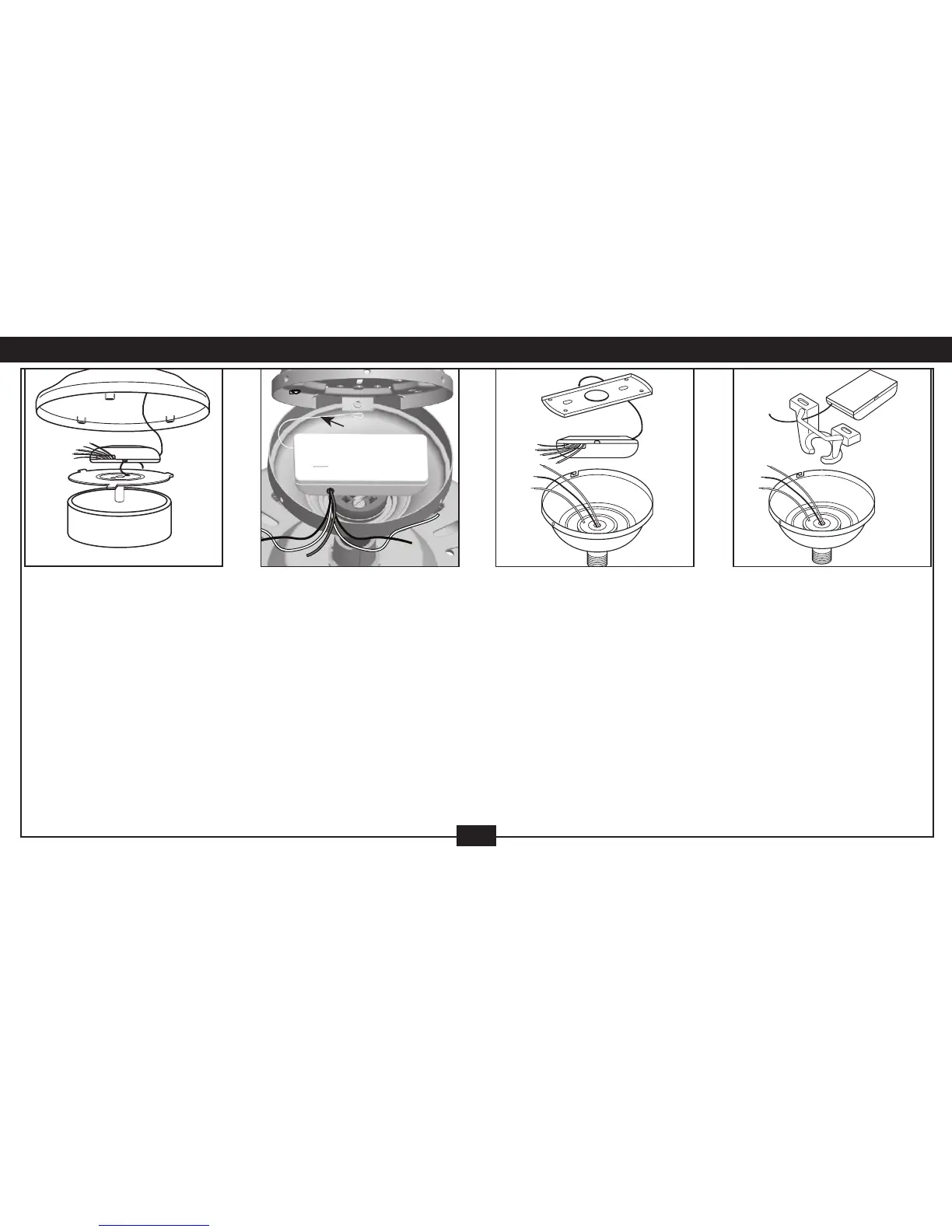
Hunter Hands-Free™
Canopy: Connect wiring as
shown in Figure 6. Place receiver
inside mounting bracket. Extend
antenna above the ceiling
mounting bracket (approximately
3–6˝).
Hands
Free
Figure 5
Bracket
Hanger
Bracket Hanger: Starting
with the antenna wire, slide
receiver inside mounting bracket.
If a ground wire mounting screw
prevents the receiver from sliding
into the bracket, move ground wire
and screw to an unused hole at
the top of the bracket or secure
with a canopy mounting screw.
The bracket must remain properly
grounded. Connect wiring as
shown in Figure 6. Extend antenna
above the receiver (approximately
3 – 6˝).
Figure 6
3 • Receiver Installation
NOTE: Some fans may have considerable excess lead wire. For easier canopy installation, cut
the excess wire leaving a minimum of 6 inches remaining. Restrip the fan lead wires 1/2 inch.
Place remaining excess wire into the ceiling electrical box as needed.
Canopy Hanger (Fig. 4):
Place receiver in canopy. Connect
wiring as shown in Figure 6.
Extend antenna through one
of the ceiling plate openings
(approximately 3–6˝).
Canopy
Antenna
Fig.
4
Low Prole Style II (Figure
3): Secure receiver to the ceiling
mounting bracket with UL-listed
cable ties (not included). Connect
wiring as shown in Figure 6.
Extend antenna above the ceiling
mounting bracket (approximately
3–6˝).
Low
Prole
Style 2
Figure 3
 Loading...