9
Site Survey/Comm Check
Verify that the WVL assembly will t in the valve box area
without interfering with the valve or other devices in the box.
1. Final installation requires a minimum 11 cm diameter
and 16 cm vertical clearance below the valve box lid.
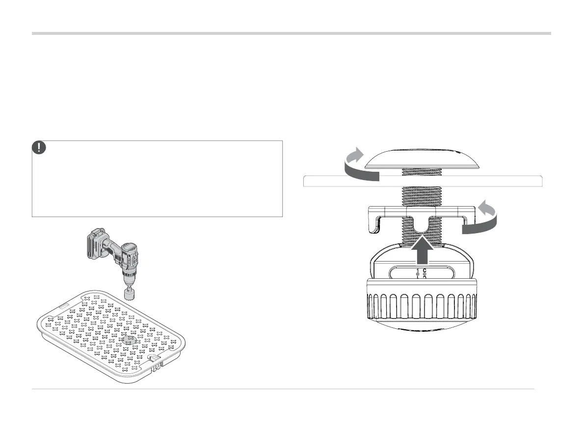
2. Determine the center point for the WVL, and drill or use the
38 mm hole saw (supplied with each WVOM-E) into the
valve box lid on the center of the WVL location.
Note: We recommended drilling upward from the underside
of the valve box lid to avoid any reinforcement ribs.
Additional trimming or modications may be required,
depending on the lid material and design. For plastic or
berglass lids, a handheld jigsaw can remove internal ribs
that a hole saw cannot.
3. Insert the WVL threaded column up through the hole. Screw
on the antenna cap above the valve box lid.
4. Use the threaded nut to tighten the connection to the
underside of the valve box lid.
Connect the station output wires to the Hunter DC-Latching