PREP~ING YOUR SAW FOR USE
A. GETTING READY
2. HAVE THE FOLLOWING AVAILABLE:
1. READ YOUR OPERATOR’S MANUAL
a.
CAREFULLY
b.
YourOperator’sManualhas beendevelopedto
c.
help ouprepareyoursawforuseandto under-
J
d.
stan itssafeoperation.It isim ortantthatyou
\
readyourmanualcompletelyto ecomefamiliar
with the unit before you begin assembl or at-
(l’
e.
tern t operation. Your HUSQVARNA ealer is
Yavai ableto showyou how to operateyour saw, Be
f.
sure to ask for his assistance.
g.
Protective gloves<
Approved, marked fuel container.
One gallon regular unleaded gasoline.
2.6 oz. 2 cycle, air-cooled engine oil (See the
“FuelingYourEngine”section).
Bar and Chain Oil (See the “Bar and Chain
Oil” section).
Scrench.
StandardScrewdriver
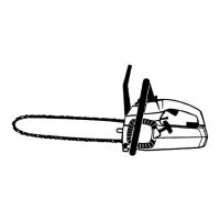
B. ATTACHING THE BAR AND CHAIN
I
Yoursaw is equipped with a Reduced-Kick-
back Bar and a Low-Kickback Chain.
Always use the Reduced-Kickback Guide
Bar and Low-Kickback Chain specified for
your chain saw model when replacing these
parts. See the “Specifications” section.
A WARNING
I
Do not start engine without guide bar and chain
completely assembled. Otherwise, the
clutch
can come off and serious injury can result.
ICAUTION. t
.
Wear protective gloves when
handling or operating saw. The chain is sharp
and can cut you even when it is not moving!
1.
2.
3.
4.
5.
6.
7.
8.
9.
10.
11.
12.
13,
Remove the following partsusing a scrench and a
standardscrewdriver.
a. Bar Clamp Nut
b. Bar Clamp Screw
c. Bar Clamp
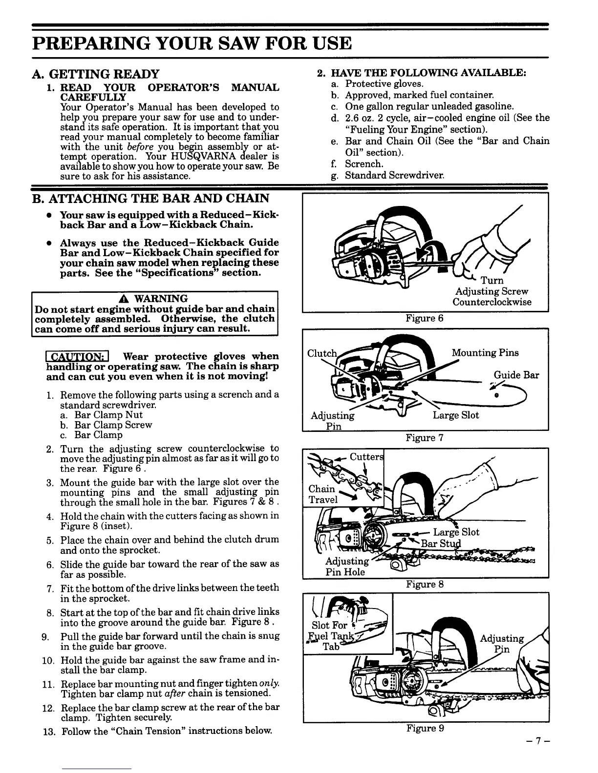
Turn the adjusting screw counterclockwise to
movethe adjustingpinalmostasfarasitwillgoto
the rear. Figure 6.
Mount the guide bar with the large slot over the
mounting pins and the small adjusting pin
through the smallhole in thebar. Figures 7 & 8.
Holdthe chainwith thecutters facing asshown in
Figure 8 (inset).
Place the chain over and behind the clutch drum
and onto the sprocket.
Slidethe guide bar toward the rear of the saw as
far aspossible.
Fitthebottom ofthedrivelinksbetweenthe teeth
in the sprocket.
Startat the top of the bar andfit chain drive links
into the groove around the guide bar. Figure 8.
Pull the guide bar forward until the chain is snug
in the guide bar groove.
Hold the guide bar against the saw frame and in-
stallthe bar clamp.
Replacebarmounting nut andfingertightenonly.
Tighten bar clamp nut afier chain is tensioned.
Replacethebar clamp screw atthe rear of the bar
clamp. Tighten securely.
Follow the “Chain Tension” instructions below.
Counterclockwise
Figure 6
+
Clutch
. .
Adj>>*~’n.~”
Large Slot
Pin
Figure 7
Figure 9
–7-
 Loading...