3
23
531 03 06-23
Model 326
Model 327 LS, 327 P5
502 50 83-01
Fuel system
ank venting
Check that the tank venting valve works
correctly.
Replace the fuel cap if the valve is faulty.
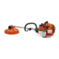
Tank venting
Tank venting takes place through the fuel
cap and needs to be functional for the
engine to work.
• Remove the fuel hose from the carbu-
rettor and empty the fuel from the tank.
• Connect the fuel hose to pressure
tester no. 531 03 06-23.
• Pump up a pressure and vacuum of 50
kPa (0.5 bar) in the tank.
• The pressure should drop to 20 kPa
(0.2 bar) or revert to atmospheric pres-
sure within 45 seconds.
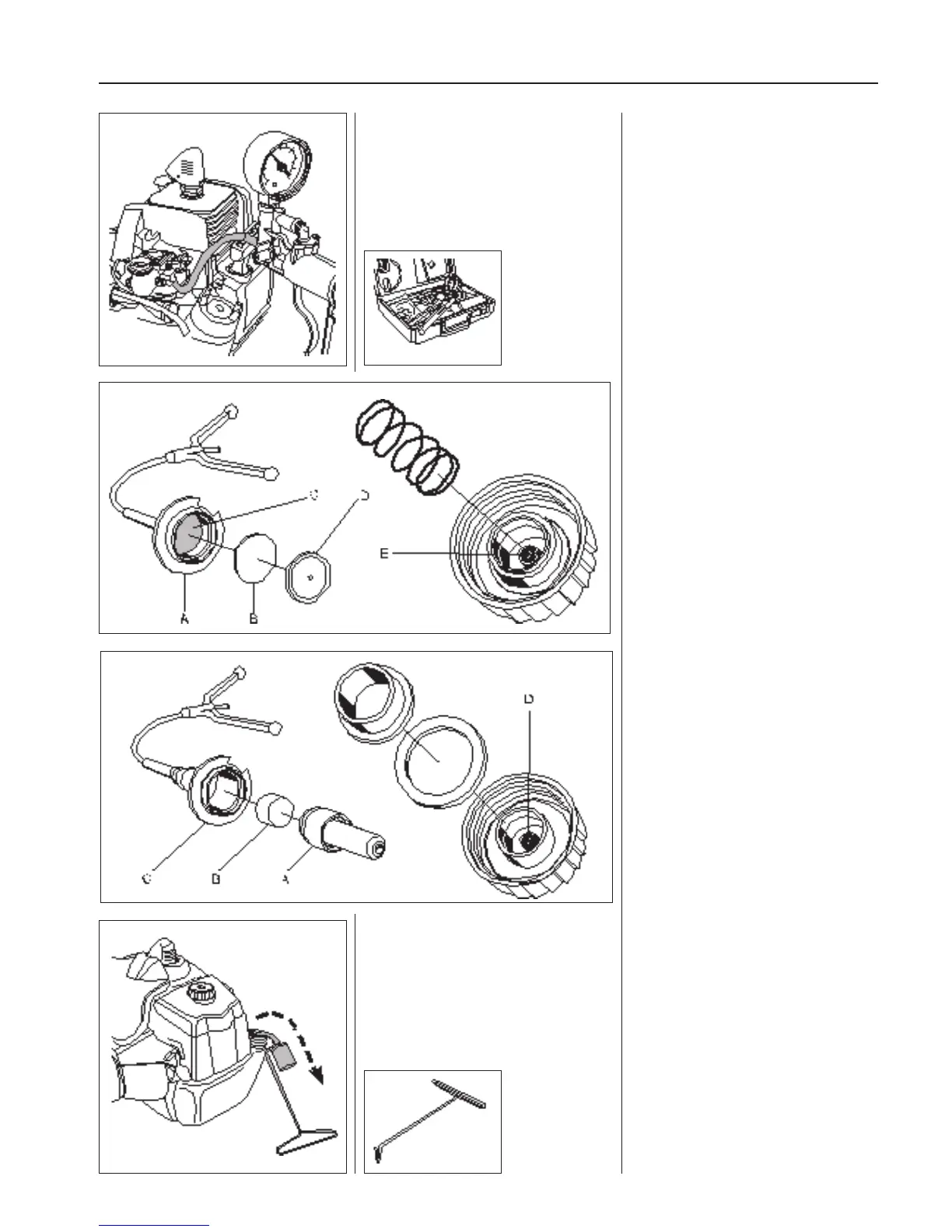
The fuel cap can be taken apart for
cleaning.
Use a screwdriver and prise o the hou-
sing (A) that contains a rubber diaphragm
(B) and a lter (C).
Knock the housing against a tabletop so
that the cover (D) over the diaphragm falls
o .
Blow the lter (C) clean, and the sintered
lter (E), with compressed air and mount
the fuel cap in the reverse order to how it
was disassembled.
Make sure that the at surface on the co-
ver (D) is turned towards the diaphragm.
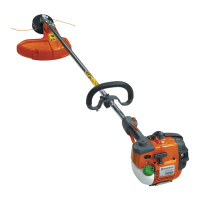
Check that the tank venting is in working
order by connecting the 531 03 06-23 test
equipment to the nipple (A). Air must be
able to ow in both directions.
If this is not the case, the lter (B) may be
blocked.
The nipple becomes accessible after
the housing (C) is rst prised o using a
screwdriver.
Blow the lter (D) clean in the tank cap
using compressed air.
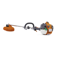
Fuel lter
The fuel lter can be removed through the
tank’s ll hole.
Fuel lter
The fuel hose in the tank contains a fuel
lter. It is accessible through the ll hole.
Pull out the lter with your ngers or with
help of tool 502 50 83-01.