6
57
Cylinder and piston
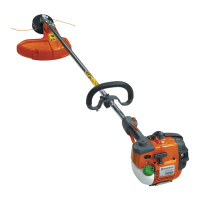
Wear tolerances
Max. 1,6 mm. Clean the
groove before checking the
measurement.
Assembly
Clean the crankcase.
Assemble the piston on the connecting
rod.
Assembly
Clean the crankcase.
Fit the piston on the connecting rod so
that the arrow on the piston points towards
the exhaust port. Lubricate the gudgeon
pin’s needle bearing with a few drops of
engine oil.
Direct the arrow on the top of the piston
towards the exhaust port. Press in the
gudgeon pin and t the circlips.
NOTE!
Place a rag in the crankcase opening to prevent the circlip from falling into the
crankcase in case it should y out. Check that the circlips are correctly tted
into the grooves by turning the clips with at nosed pliers.
Fit the cylinder on the crankcase.
Alternative
Fit the crankshaft/piston rst to the cylin-
der and the place the unit on the crank-
case.
Check that both gasket halves are unda-
maged and are positioned correctly on the
crankcase (also see chapter. 7).
Lubricate the piston using a few drops of
oil and carefully slide the cylinder over the
piston.
NOTE!
Do not turn the cylinder, as the piston rings can easily be broken.
Check that the cylinder is tted so that the crankshaft’s ball bearing is in the
same position in the bearing seating as it was before dismantling. Otherwise
there is a risk that leakage can occur between the bearing and cylinder.
Tighten the 4 screws diagonally crosswise.
Assemble the remaining parts in the re-
verse order as set out for dismantling.
Assemble the remaining parts in the re-
verse order as set out for dismantling.
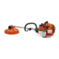
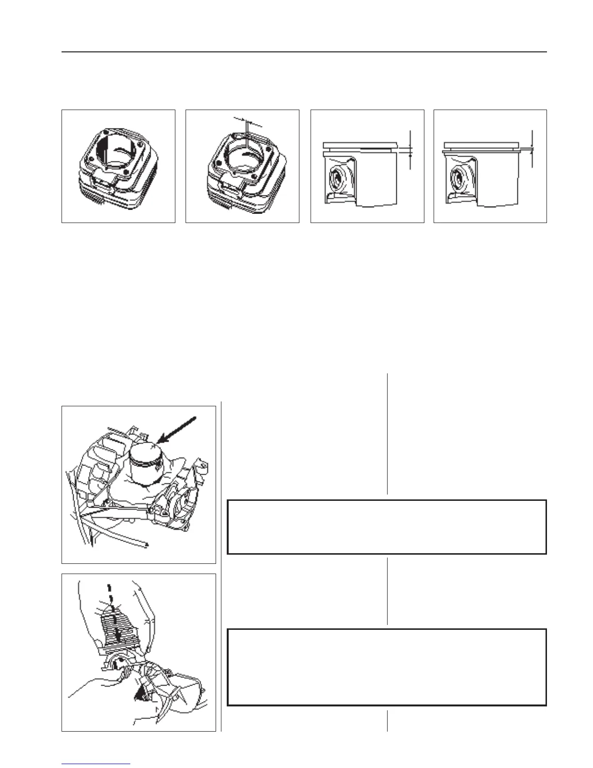
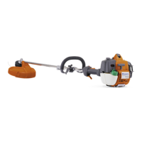
Cylinder bore Piston ring gap Piston ring groove Piston ring play
When the surface coating is
worn and aluminium ap-
pears.
Max. 1.0 mm with the piston
ring inserted in the lower
part of the cylinder.
Max. 0.15 mm. Clean the
groove before checking the
measurement.