3
30
531 03 06-23
Fuel system
Attach the various parts of the measuring
unit in the reverse order as set out for
dismantling.
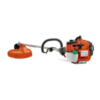
The lever arm should lie ush with the
carburettor housing.
Attach the various parts of the measuring
unit in the reverse order as set out for
dismantling.
The lever arm should lie ush with the
carburettor housing.
Too high setting = too much fuel.
Too low setting = too little fuel.
NOTE!
The H-needle is a little shorter than
the L-needle.
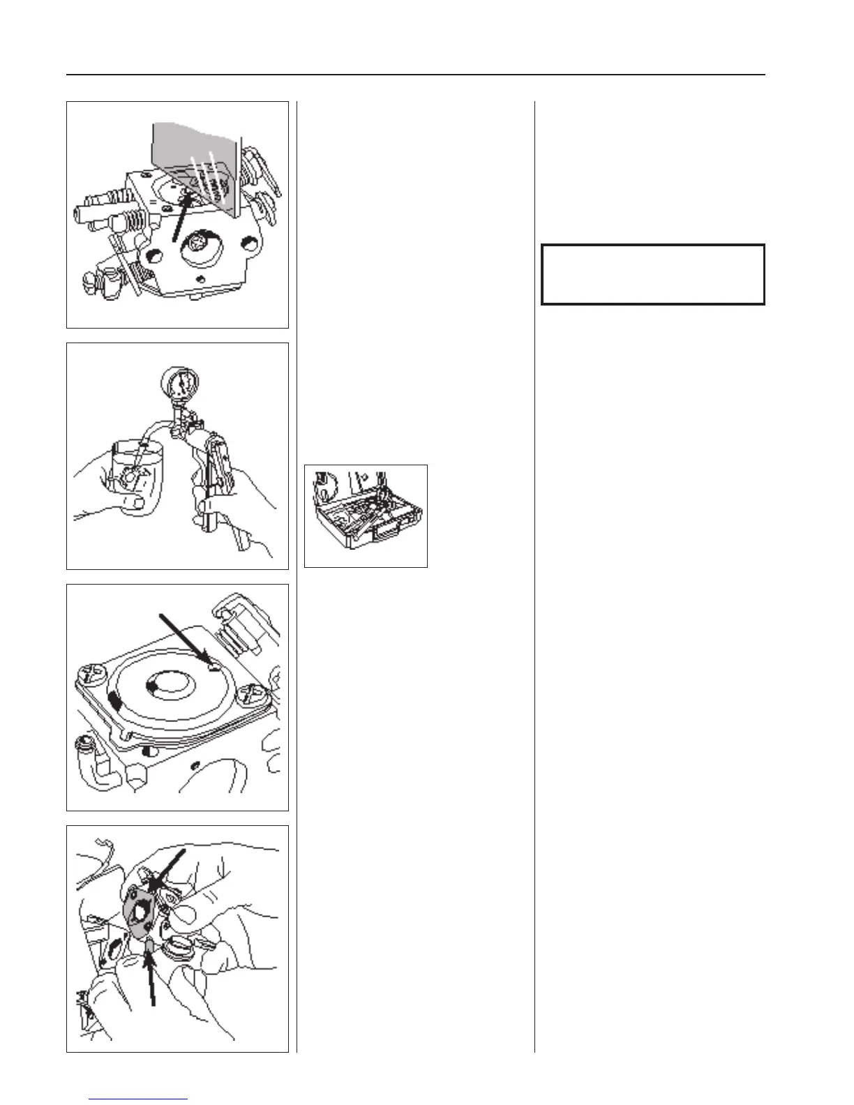
Check that the carburettor is sealed.
No leakage is permitted at 50 kPa.
Connect pressure tester 531 03 06-23 to
the fuel intake on the carburettor.
Pump up the pressure to 50 kPa.
Lower the carburettor in a vessel with
petrol in order to discover any leaks more
easily.
No leakage is permitted.
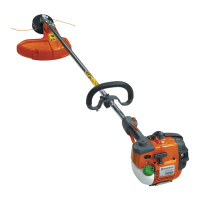
Attach the control diaphragm and cover.
Place the gasket on the carburettor
housing and then the control diaphragm.
Check that the air hole in the cover is
open and screw the cover on.
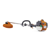
Assembly
Secure the seal on the carburettor and
connect the fuel pipe.
Place the carburettor between the air lter
connection and distance piece.
Tighten the carburettor screws.
Assembly
1. Secure the seal on the carburettor with
a little grease.
2. Connect the fuel pipe from the tank.
3. Slide in the carburettor between the air
lter connection and the distance piece
on the cylinder.
4. Tighten the carburettor screws and
ensure that the seal is positioned
correctly.