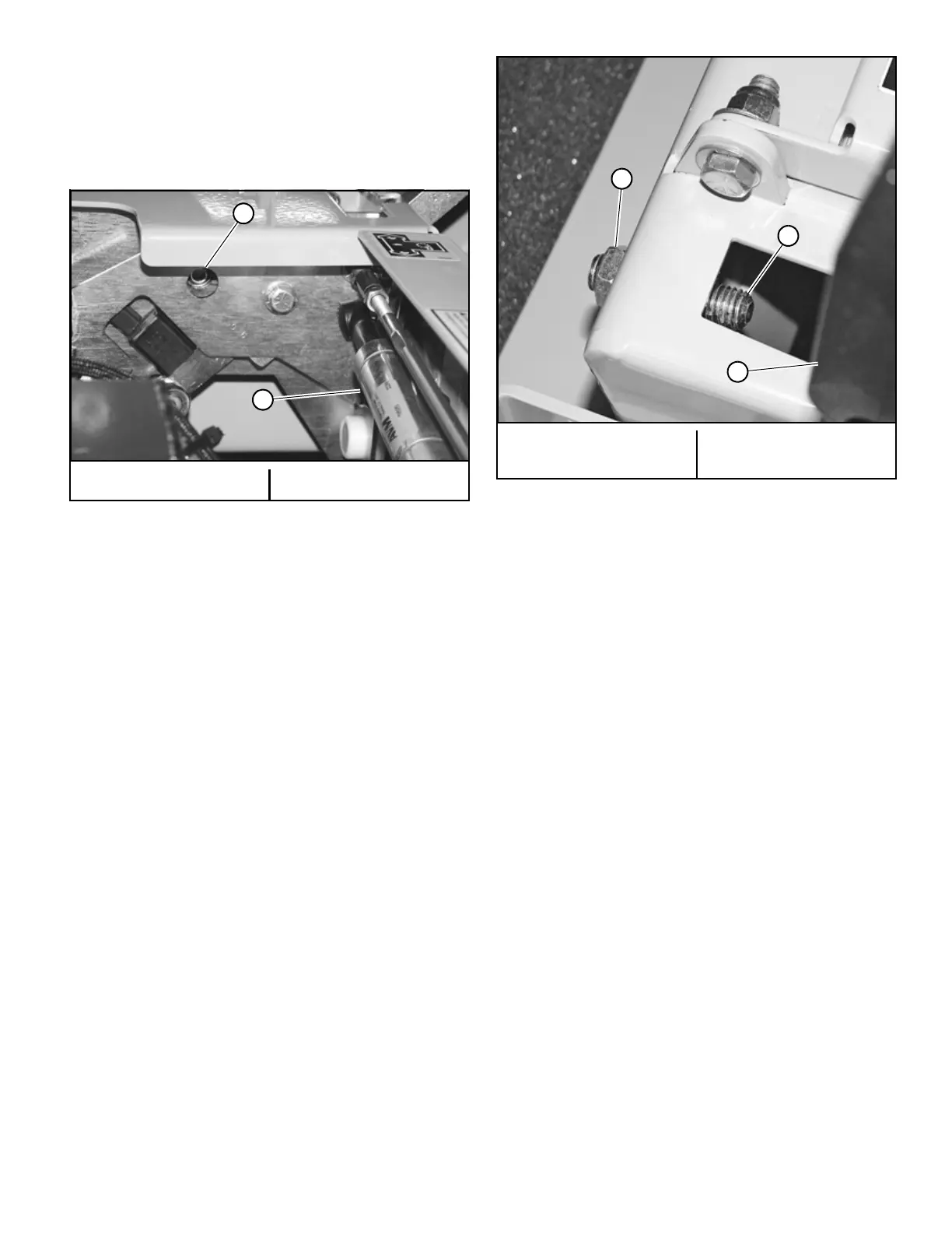
125816 4-3 REV B
arms are stopping the forward motion of the control
arms, loosen the jam nut on the adjustable stop of the
corresponding side, turn the stop (set screw) inward to
stop the steering control levers slightly before the
pump bottoms out. Lock in place when the adjustment
is correct by re-tightening the jam nut. Do this for each
side. Figure 4-4
To adjust the stops for driving straight when steering
control levers are against the stops during operation:
1. Determine which drive tire is rotating too fast when
both steering control levers are against the stops in
the control panel (see Figure 4-5).
2. Then, stop the mower and loosen the lock nut on the
side which is rotating too fast and turn the stop (set
screw) inward to stop the steering control lever
sooner. Tighten the lock nut on the stop and test
again.
3. Repeat this procedure until unit drives straight.
NOTE: Since this is a hydrostatic drive, variables such as
temperature of oil, efficiency of pumps and motors, tire pres-
sure etc. may affect the consistency of the ability to rely on
the stops to drive straight without the operator making minor
steering adjustments with the control arms.
Steering Damper
The steering dampers are spring loaded to return the
control levers to the neutral position from the reverse
position. This gives the operator a sense of neutral during
operation.
To set the steering dampers in the correct operating
position follow these steps:
1. Shut engine off, place steering control levers in the
park brake position, disengage deck clutch, remove
ignition switch key and disconnect negative battery
cable before doing any adjustments.
2. Place the steering control lever in the neutral position.
Figure 4-6
3. Loosen the steering damper’s rear ball stud. Figure 4-7
4. Pull the damper spring housing past the point that the
internal spring is engaged. Figure 4-7
5. Release the damper spring housing and allow the
internal spring to bring the housing back to the neutral
position.
6. Tighten the nut on the steering damper’s front ball
stud.
NOTE: The damper must not bottom out when the pump
lever is fully stroked in either direction.
7. Reconnect the negative battery cable.
8. Lower and secure the seat platform.
9. To check, move the steering control lever to the
reverse position and release. The steering control lever
should return to the neutral position. If not, repeat
steps 1 through 6.
Steering Control Lever Adjustment
The steering control levers can be adjusted for operator
comfort.
1. By loosening the cap screws that attach the upper
control lever to the lower lever the upper control lever
can be pivoted to fit the operator’s personal preference
(see Figure 4-8).
2. The steering control levers should be adjusted so that
they align vertically with each other when in the
neutral position. Figure 4-9
A. Stop screw B. Steering damper
Figure 4-4
A. Jam nut
B. Stop
C. Steering control lever
Figure 4-5
 Loading...