125816 6-3 REV B
5. Lower the center deck to rest against the stop pin.
6. Set the deck cutting height for the front and rear side
deck gauge wheels at 3-1/4” (82.6 mm). Figure 6-7
7. Place a 3” (76.2 mm) high deck support block (two
stacked 2” x 4” blocks can be used to create a 3”
[76.2 mm] high support) at the outside edge of the side
deck. Figure 6-3 & Figure 6-8
8. Lower the side decks to fully rest on the 3” (76.2 mm)
blocks.
9. Loosen the two 1/2” bolts on the rear gauge wheel
arm. Loosen the jam nut and adjusting bolt so the rear
gauge wheel is not supporting any of the weight of the
side deck. Figure 6-9
10. The front gauge wheel should contact the ground. If
so, skip to Step 11. If not, the gauge wheel will need
adjusted down per Step 12.
11. There should be less than .125” (3.18 mm) gap
between the 3” deck block and the bottom side of the
deck edge. Figure 6-8
If so, go to Step 13. If not, the gauge wheel will need
adjusted up per Step 12.
12. Adjust the front gauge wheel up or down to satisfy
your deck adjustment needs.
Adjustments are made by removing the front wheel
from the wheel tube and re-arranging the two .125”
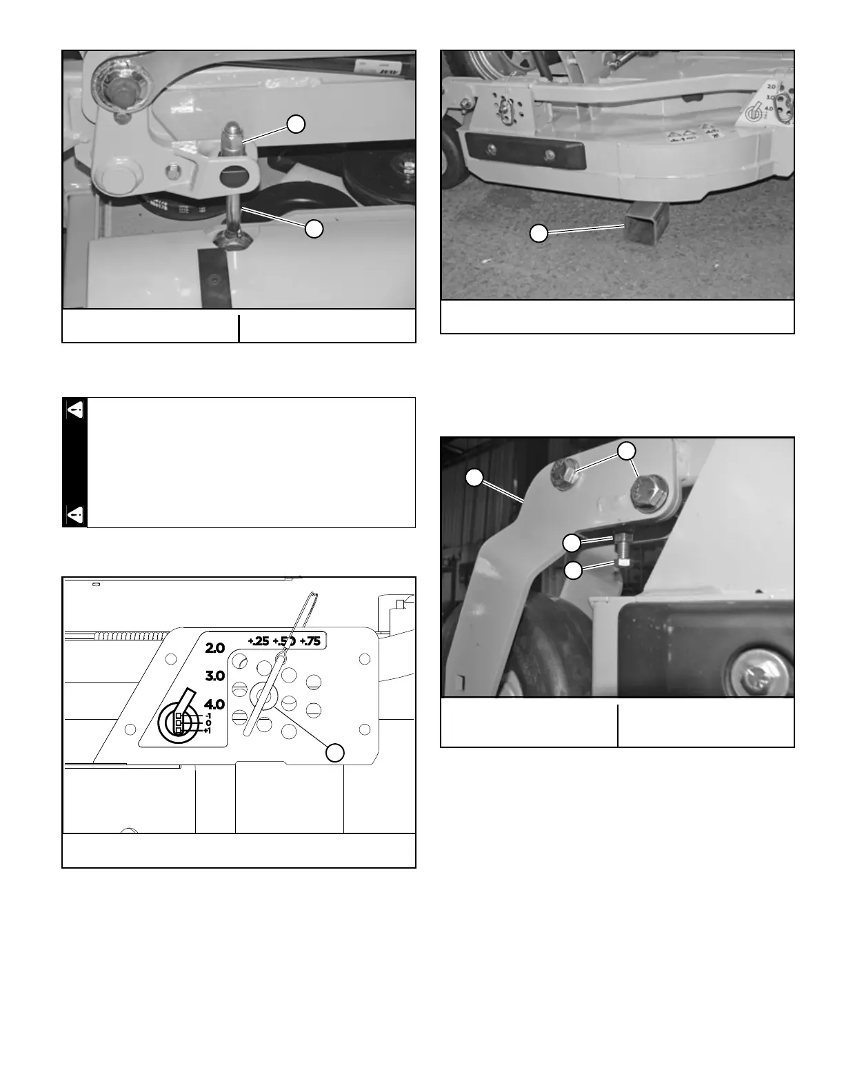
(3.18 mm) and one .25” (6.35 mm) spacers located
A. Nut B. Deck lift hanger
Figure 6-6
Stop engine. Make sure deck clutch switch is in
the down (OFF) position. Place control levers in the
brake position before leaving machine.
A. Set deck cutting height at 3–1/4"
Figure 6-7
A. 3" (76.2 mm) block
Figure 6-8
A. Rear wheel arm
B. 1/2" bolts
C. Jam nut
D. Adjusting bolt
Figure 6-9
 Loading...