Driven Element
Assembly
( ) Now select the 02 sections (3/8" x 53-1/4") and slip the drilled end
into the 01 section. Line up the holes and fasten securely using #8 x 3/8"
self-tapping screws.
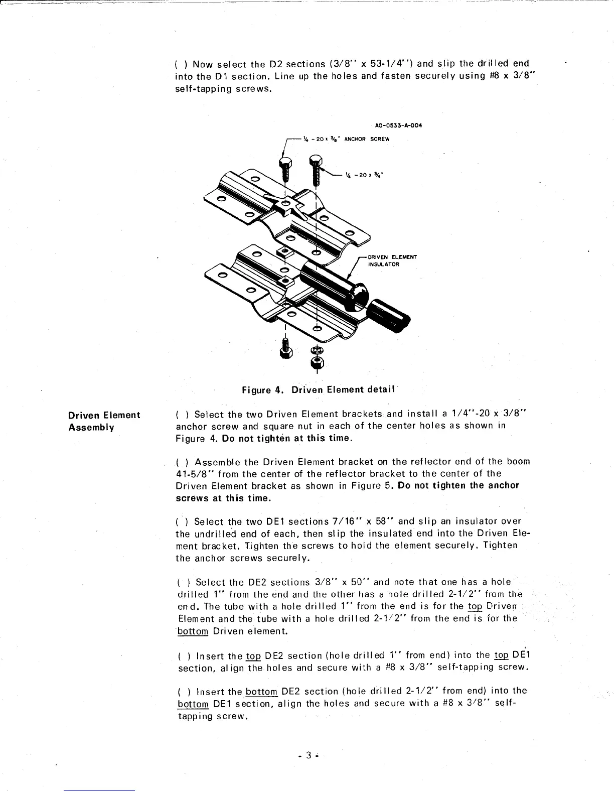
( ) Select the two Driven Element brackets and install a 1/4"-20 x 3/8"
anchor screw and square nut in each of the center holes as shown in
Figure 4. Do not tighten at this time.
( ) Assemble the Driven Element bracket on the reflector end of the boom
41-5/8" from the center of the reflector bracket to the center of the
Driven Element bracket as shown in Figure 5. Do not tighten the anchor
screws at this time.
( ) Select the two DE1 sections 7/16" x 58" and slip an insulator over
the undrilled end of each, then slip the insulated end into the Driven Ele-
ment bracket. Tighten the screws to hold the element securely. Tighten
the anchor screws securely.
( ) Select the DE2 sections 3/8" x 50" and note that one has a hole
drilled 1" from the end and the other has a hole drilled 2-1/2" from the
end. The tube with a hole drilled 1" from the end is for the!2..e Driven
Element and the tube with a hole drilled 2-1/2" from the end is for the
bottom Driven element.
( ) Insert the!..Q..QDE2 section (hole drilled 1" from end) into the!QQ DE1
section, align the holes and secure with a #8 x 3/8" self-tapping screw.
( ) Insert the bottom DE2 section (hole drilled 2-1/2" from end) into the
bottom DE1 section, align the holes and secure with a #8 x
3
/
8"
self-
tapping screw.