Installation Manual 5.1.2
12
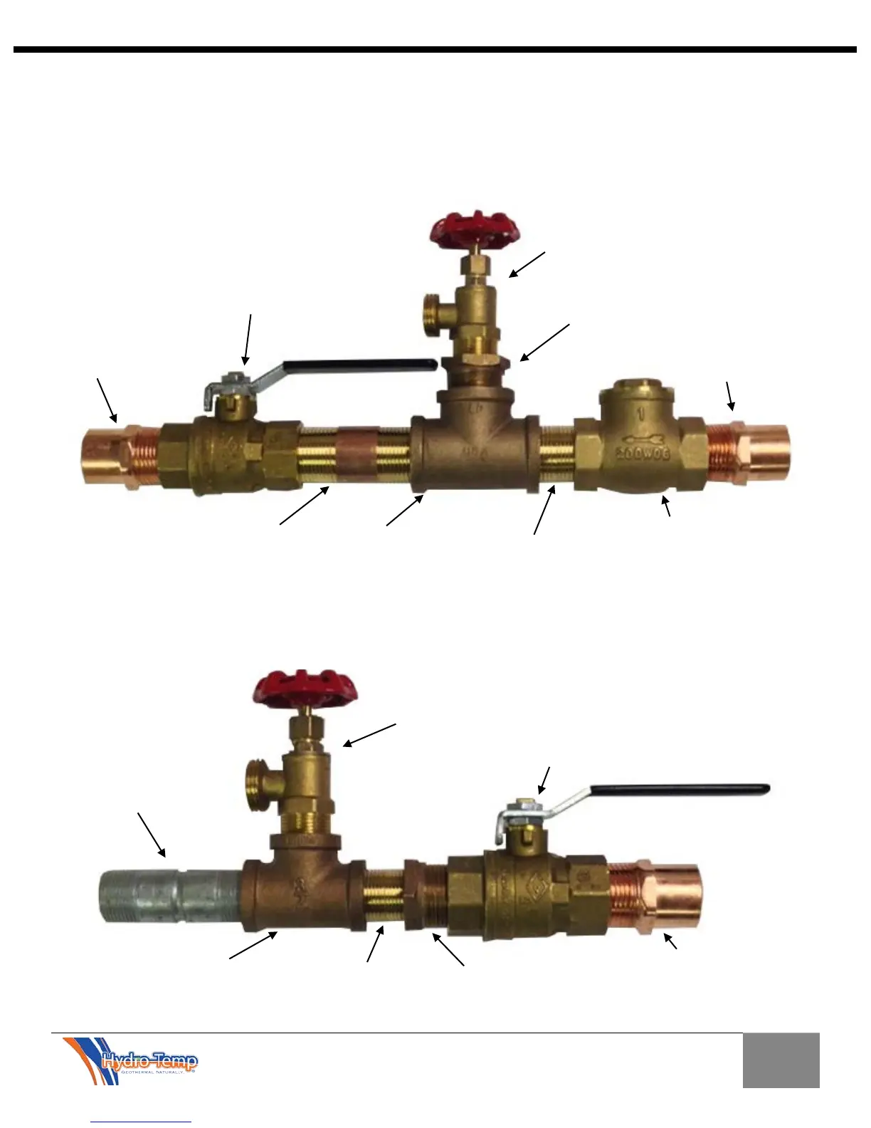
check valve
adapter
Standard hose fitting / Boiler drain A
with ¾” MPT
threaded bushing
Standard hose fitting / Boiler
drain B with ¾” MPT
Valve B
(connects to
bottom of water
heater after boiler
drain is removed)
adapter
threaded bushing
UPPER DHW Plumbing Fittings (connecting into cold water line on the top of the tank)
*Important: 1.) All fittings on the cold water line where the plumbing (below) connects to the
tanks cold water line must be either copper, brass, bronze, or steel from 12” above the “T” to the
tank.
2.) No other water lines can be connected between the “T” and the tank.
LOWER DHW Plumbing Fittings (connecting into bottom of the tank)
*Important: Most water heaters have ¾” fittings. It is important to increase pipe sizing to 1”
(3-6 Ton Priority water heating units) in as short a distance as possible in order to assure proper
Refer to figure 5.2 and 5.3 for plumbing details
Refer to figure 5.2 and 5.3 for plumbing details
adapter (“T’s”
into cold water
line directly
above tank)
Valve A