MAX200 Product Configuration Manual2-2
Programmable
Remote V/C
CNC
Interface
(customer
supplied)
Torch
WM
IHS
Console
Air Reg.
Second
MAX200
Power
Supply
WM
Pump
Digital
Remote V/C
Switch
Remote V/C
Remote
Current
Control
MAX200
Power
Supply
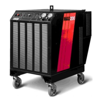
1 MAX200 Power Supply (PS)
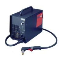
2 Machine Torch Assembly
3 Leads Between Power Supply and Torch
4 Machine Interface Cable Between Power Supply and
CNC Interface
5 Programmable Remote Voltage & Current Control
6 Cable Between Power Supply and Programmable Remote or
Digital Remote
7 Cable Between Programmable Remote and CNC Interface
8 Digital Remote Voltage & Current Control
9 Switch Remote Voltage & Current Control
10 Cable Between Power Supply and Switch Current
11 Remote Current Control
12 Cable Between Power Supply and Current Remote
13 Inductive IHS System
14 IHS Pressure Regulator Assembly
15 Inductive IHS Lead Set
16 Water Muffler System (not used with the stainless steel torch)
17 Additional Length WM Hose
18 Cable Between Water Muffler Pump and Power Supply
19 Work Cable Between Power Supply and Work Table
20 Hold Cable Between Power Supplies
MAX200 Machine System Block Diagram
 Loading...