

S
swelchJul 27, 2025
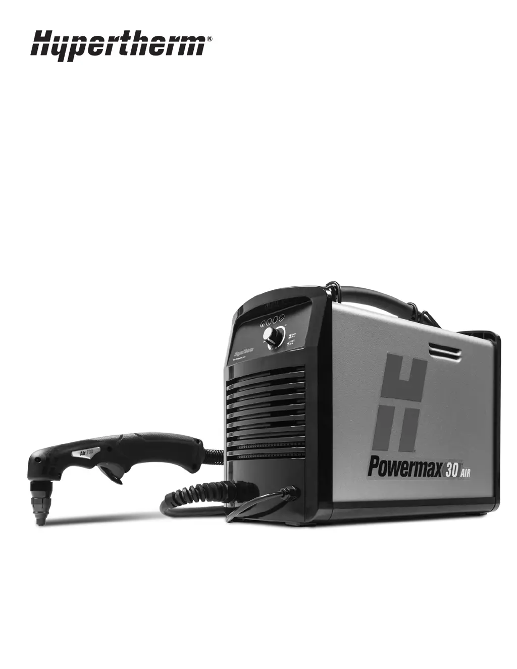
How to fix a dry, cracked, or worn torch O-ring on a Hypertherm Welding System?
- MMichael RoachJul 27, 2025
If the torch O-ring is dry, apply a thin film of silicone lubricant on the O-ring and the threads. The O-ring should look shiny, but there should not be any excess or built-up lubricant. If the O-ring is cracked or worn, replace it.


