EasyManuals Logo

Hypertherm Powermax30 AIR Service Manual

Hypertherm Powermax30 AIR
223 pages
To Next Page IconTo Next Page
To Previous Page IconTo Previous Page
Page #196 background imageLoading...
Page #196 background image
196 Powermax30 AIR Service Manual 808850
7 Torch Component Replacement
Replace the cap-sensor switch
1. Complete the following procedures:
a. Set the power switch to OFF (O), and disconnect the power cord from the power source.
b. Remove all components from the torch. See Remove the handle on page 187.
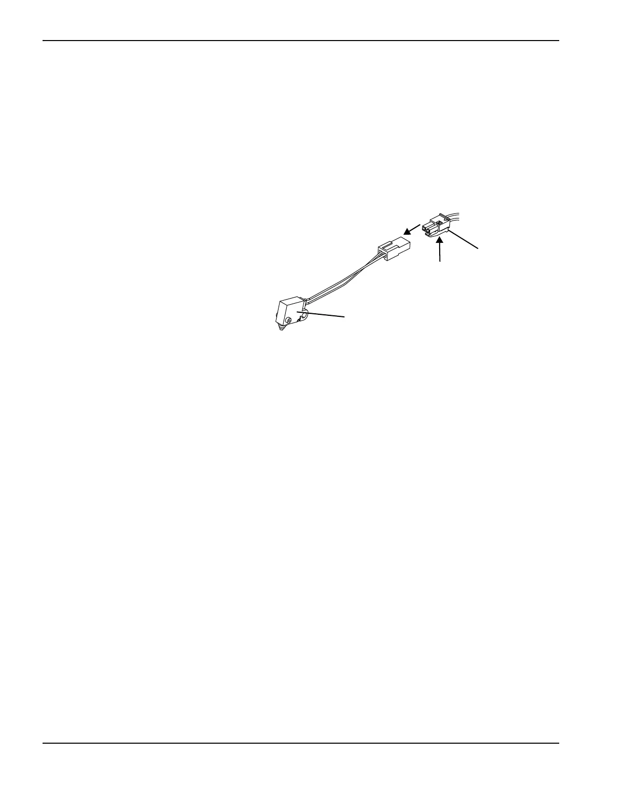
2. Disconnect the old cap-sensor switch by
pressing the tab on the connector and pulling
the connector apart.
3. Connect the new cap-sensor switch to the
torch lead by pushing the mating plug on the
torch lead wires into the socket.
4. Complete the following procedures:
a. Install all of the torch components that you
removed. See Install the handle on
page 190.
b. Reconnect the power cord, and set the power switch to ON (I).
Kit Description
228109 Kit: Torch cap-sensor switch
Cap-sensor switch
Tab

Table of Contents

Other manuals for Hypertherm Powermax30 AIR

Questions and Answers:

Question and Answer IconNeed help?

Do you have a question about the Hypertherm Powermax30 AIR and is the answer not in the manual?

Hypertherm Powermax30 AIR Specifications

General IconGeneral
Built-in Air CompressorYes
Output Voltage83 VDC
Input Voltage120-240 V
Current Output15–30 A
Cutting ThicknessUp to 10 mm (3/8 in) recommended cut
Gas SupplyBuilt-in air compressor
Operating Temperature-10°C to +40°C (+14°F to +104°F)

Related product manuals