EasyManuals Logo

Hypertherm Powermax30 AIR Service Manual

Hypertherm Powermax30 AIR
223 pages
To Next Page IconTo Next Page
To Previous Page IconTo Previous Page
Page #204 background imageLoading...
Page #204 background image
204 Powermax30 AIR Service Manual 808850
8 Parts
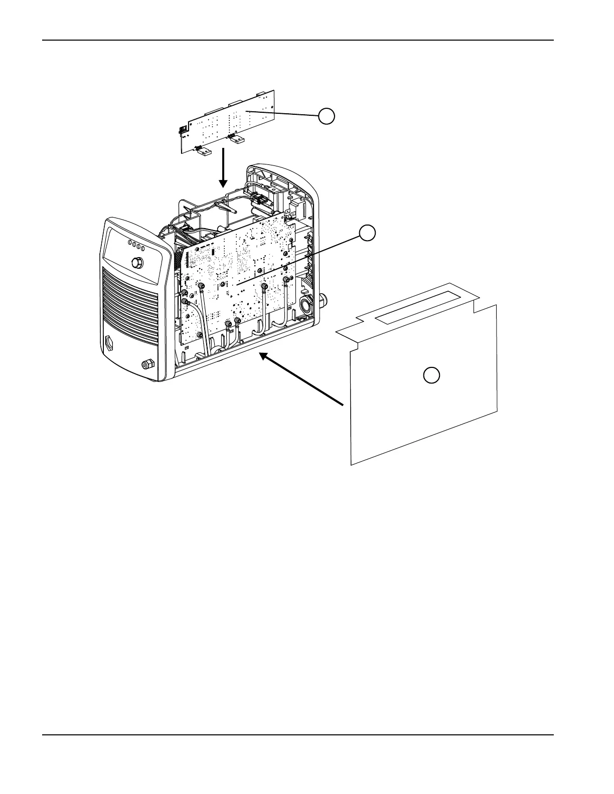
Interior, power board side
Item Kit number Description Designator
1 428395 Kit: Component barrier
2 428402 Kit: Power board, CSA (141351) PCB2
2 428403 Kit: Power board, CE (141357) PCB2
3 428401 Kit: Compressor-driver board (includes thermal strips and
polyimide tape) (141298)
PCB3
428406 Kit: Replacement clips (not shown):
Replacement clip and screws for snubber resistor on
power board
Replacement clips and screws for MOSFET and
diode on compressor-driver board
428411 Kit: Replacement hex nut standoffs (5) for mounting power
board to heatsink (not shown)
1
3
2

Table of Contents

Other manuals for Hypertherm Powermax30 AIR

Questions and Answers:

Question and Answer IconNeed help?

Do you have a question about the Hypertherm Powermax30 AIR and is the answer not in the manual?

Hypertherm Powermax30 AIR Specifications

General IconGeneral
Built-in Air CompressorYes
Output Voltage83 VDC
Input Voltage120-240 V
Current Output15–30 A
Cutting ThicknessUp to 10 mm (3/8 in) recommended cut
Gas SupplyBuilt-in air compressor
Operating Temperature-10°C to +40°C (+14°F to +104°F)

Related product manuals