42 Powermax30 AIR Service Manual 808850
4 – Operation
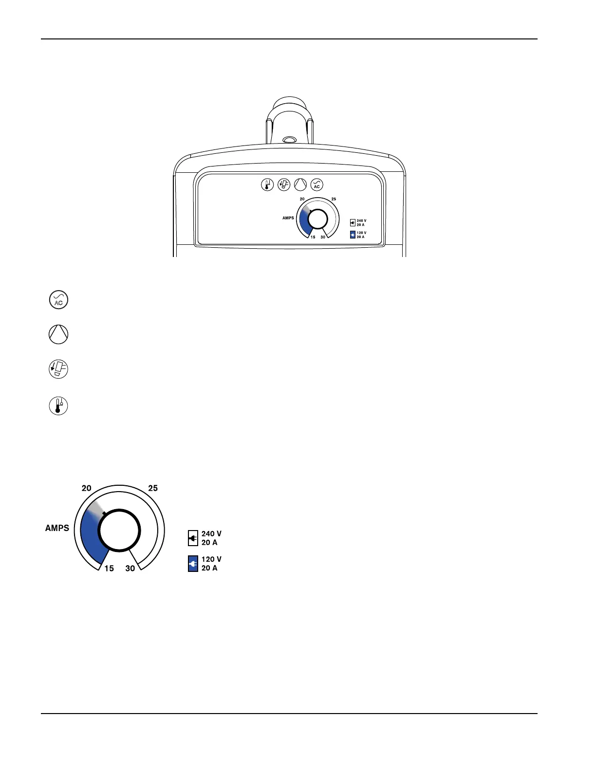
Front panel controls and indicator LED symbols
Power ON LED (green) – When illuminated, this LED indicates that the power switch has been set to ON (I)
and that the safety interlocks are satisfied.
Internal compressor LED (yellow) – When illuminated, this LED indicates a possible issue with the internal
air compressor.
Torch cap LED (yellow) – When illuminated, this LED indicates that the consumables are loose, improperly
installed, or missing.
Temperature LED (yellow) – When illuminated, this LED indicates that the system’s temperature is outside
the acceptable operating range.
Some fault conditions cause multiple LEDs to illuminate or blink at the same time. For
information on what these fault conditions are and how to clear them, see
Troubleshooting guide on page 63.
Amperage adjustment knob – Use this knob to set the output current
between 15 A and 30 A.