Powermax30 AIR Service Manual 808850 95
5 – Troubleshooting and System Tests
Test 9d – Check the power board
23. Set the power switch to OFF (O).
24. Remove the J1 and J3 connectors from the compressor-driver board. This isolates the power board.
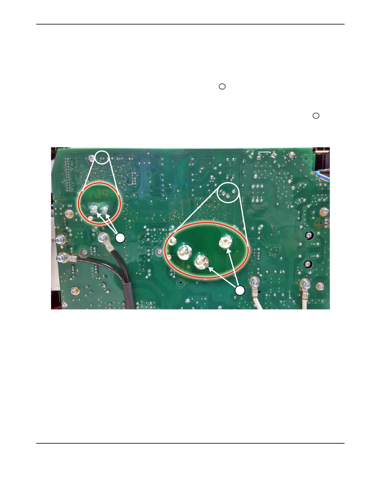
25. Check VBUS on the power board (nominal 375 VDC bus voltage) .
26. Set the power switch to ON (I).
27. Quickly tap the torch trigger, then check compressor-enable voltage at J9 on the power board (3 VDC) .
Figure 21
28. Are VBUS and compressor-enable voltage present on the power board?
a. If VBUS and compressor-enable voltage are both present on the power board, replace the
compressor-driver board. See Replace the compressor-driver board on page 121.
b. If neither VBUS nor compressor-enable voltage are present on the power board, replace the power board.
See Replace the power board on page 126.
c. If VBUS or compressor-enable voltage is present on the power board but the other is not, replace the power
board. See Replace the power board on page 126.