82 Powermax30 AIR Service Manual 808850
5 – Troubleshooting and System Tests
Test 3 – VBUS and voltage balance on power board
Test the power board (PCB2) to make sure the circuits are balanced. The test points are labeled on the back of the
power board, as are the voltages and positive and negative capacitor terminals. See Figure 13 on page 83 for locations
of test points.
1. Set the power switch to OFF (O), and disconnect the power cord from the power source.
2. Remove the power supply handle and cover. See Remove the power supply cover on page 98.
3. Remove the component barrier. See Remove the component barrier on page 100.)
4. Reconnect the electrical power.
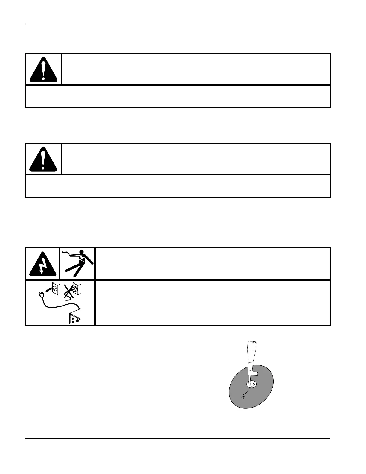
5. For each of the following 3 steps, carefully connect
the test hooks to the edges of the holes in the power
board so that the hook makes contact with the ring
on the back side of the power board.
CAUTION!
Do not use -VBUS (W) as ground. Doing so could destroy the power supply. Instead ground to either
the ground wire clip on the rear panel or to the heatsink. See Figure 5 on page 73.
CAUTION!
Do not use a multimeter with test leads. This can cause a short-circuit between the BUS and the
heatsink. Use test hook leads instead, and attach them to the test point loops.
WARNING!
ELECTRIC SHOCK CAN KILL
Use extreme caution when working near live electrical circuits. Dangerous
voltages exist inside the power supply that can cause serious injury or death.
See the WARNING! on page 57 before proceeding.