58 Powermax30 AIR Service Manual 808850
5 – Troubleshooting and System Tests
Test equipment
Multimeter with a variety of test leads, including test hooks.
Troubleshooting procedures and sequence
When performing the troubleshooting procedures, refer to:
Safety and Compliance Manual (80669C) for detailed safety information.
Powermax30 AIR schematic on page 222 for the system’s electrical schematic.
Power Supply Component Replacement on page 97 or Torch Component Replacement on page 185 for
replacement procedures.
Parts on page 201 for power supply components and torch components.
After the problem has been located and repaired, refer to Sequence of operation on page 56 to test the power supply for
proper operation.
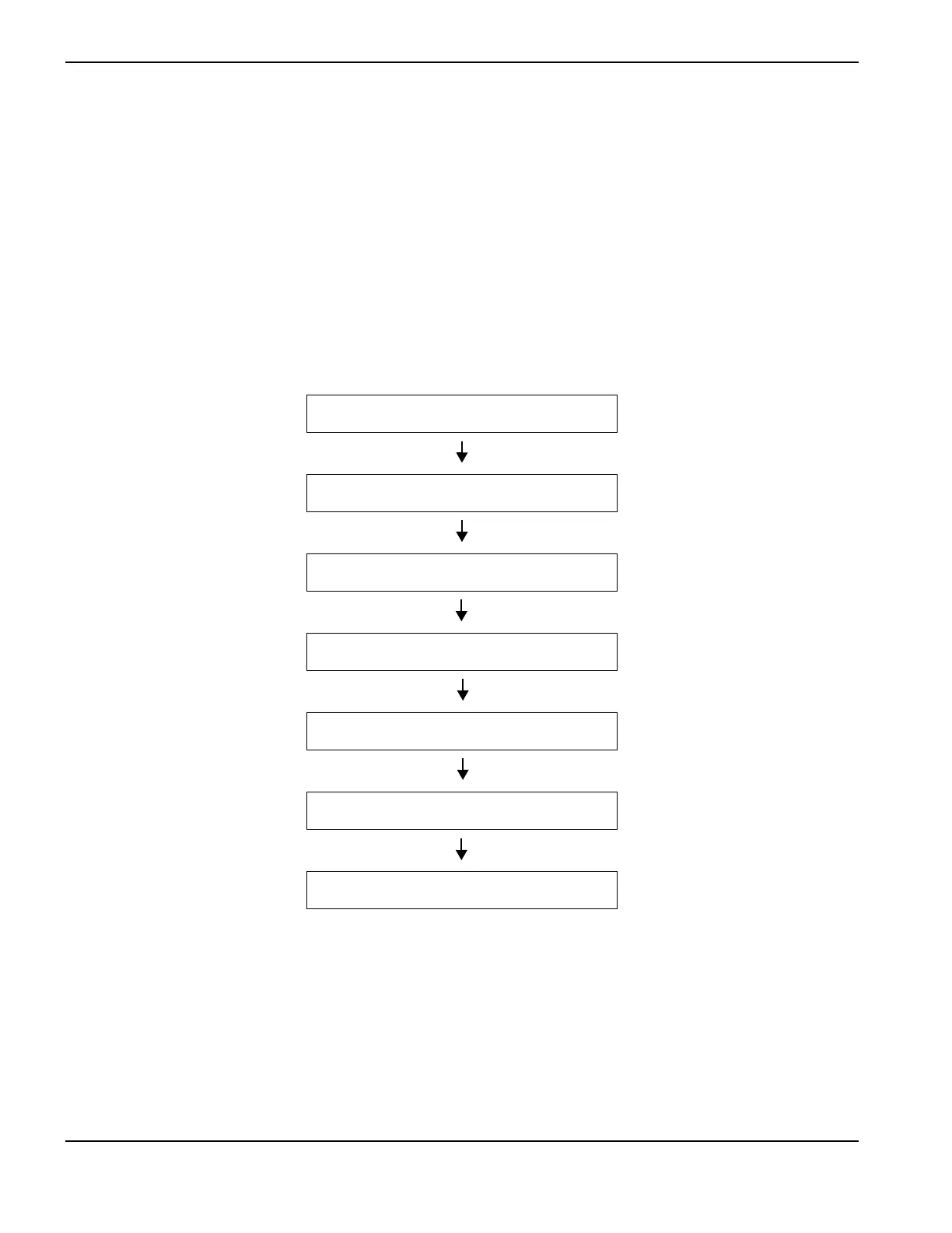
Power OFF (O) and disconnected
External inspection
Internal inspection
Initial resistance check
Power ON (I)
Troubleshooting guide
System tests