80 Powermax30 AIR Service Manual 808850
5 – Troubleshooting and System Tests
Test 2 – power board voltage checks
1. Set the power switch to OFF (O), and disconnect the power cord from the power source.
2. Remove the power supply handle and cover. See Remove the power supply cover on page 98.
3. Remove the component barrier. See Remove the component barrier on page 100.
4. Reconnect the electrical power and set the power switch to ON (I).
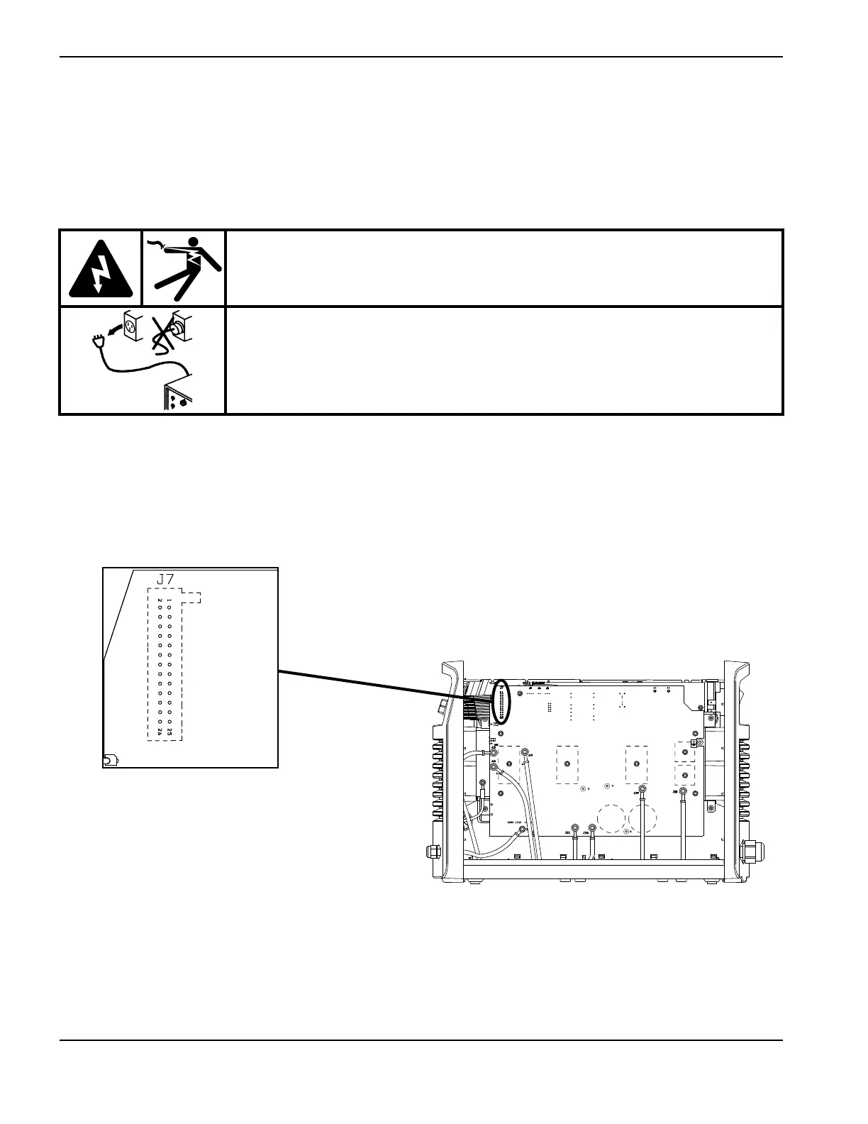
5. Use a multimeter to verify the voltages at the J7 pins listed in Table 6 on page 81 to make sure the power board
(PCB2) is functioning correctly. If any of the values are incorrect, replace the power board. See Replace the power
board on page 126.
Figure 12
To test the values at pin 16, you must position the torch and power supply so that you can
safely pull and release the torch trigger. For ground locations, see Figure 5 on page 73.
WARNING!
ELECTRIC SHOCK CAN KILL
Use extreme caution when working near live electrical circuits. Dangerous
voltages exist inside the power supply that can cause serious injury or death.
See the WARNING! on page 57 before proceeding.
WORK LEAD (BLK)
AC AC
R
w
TORCH
START
BLK
BLK
B
TORCH
START