Powermax30 AIR Service Manual 808850 93
5 – Troubleshooting and System Tests
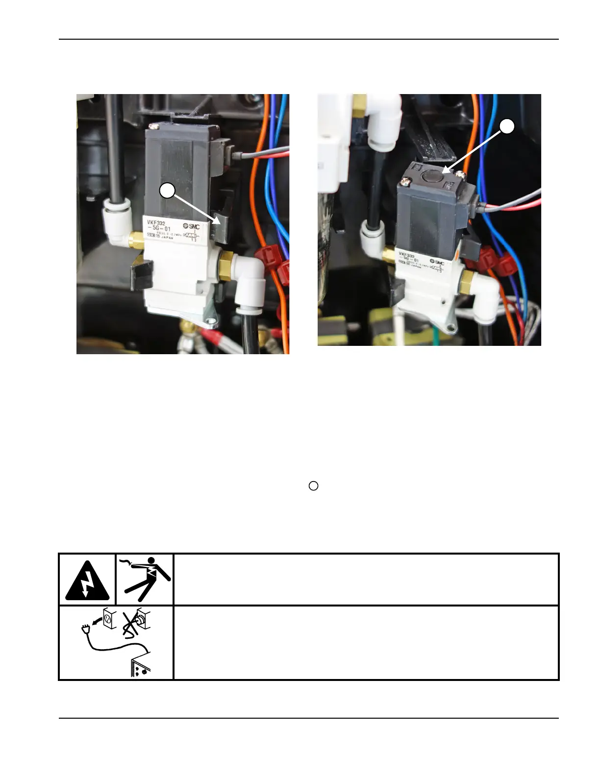
Figure 19
14. Push the solenoid valve back into place between both clips from the center panel.
15. Make sure both of the solenoid valve’s gas supply hoses are connected securely to their fittings.
Test 9c – Check the compressor-driver board
16. Set the power switch to OFF (O).
17 . Remove the white cap from the top of the J3 connector on the compressor-driver board. See Figure 20 on
page 94.
You may need to unplug the J3 connector in order to remove the white cap. If you do, plug
the connector back in before continuing with the next step.
WARNING!
ELECTRIC SHOCK CAN KILL
Use extreme caution when working near live electrical circuits. Dangerous
voltages exist inside the power supply that can cause serious injury or death.
See the WARNING! on page 57 before proceeding.