126 Powermax30 AIR Service Manual 808850
6 – Power Supply Component Replacement
Replace the power board
Although there are some technical differences between the power board for CSA power supplies and the power board
for CE power supplies, the procedure to replace the boards is the same.
Remove the power board
1. Complete the following procedures:
a. Set the power switch to OFF (O), and disconnect the power cord from the power source.
b. See Remove the power supply cover on page 98.
c. See Remove the component barrier on page 100.
d. See Detach the front panel on page 102.
2. Make sure the J7 connector from the control board is removed from the power board. See Figure 48 on page 127.
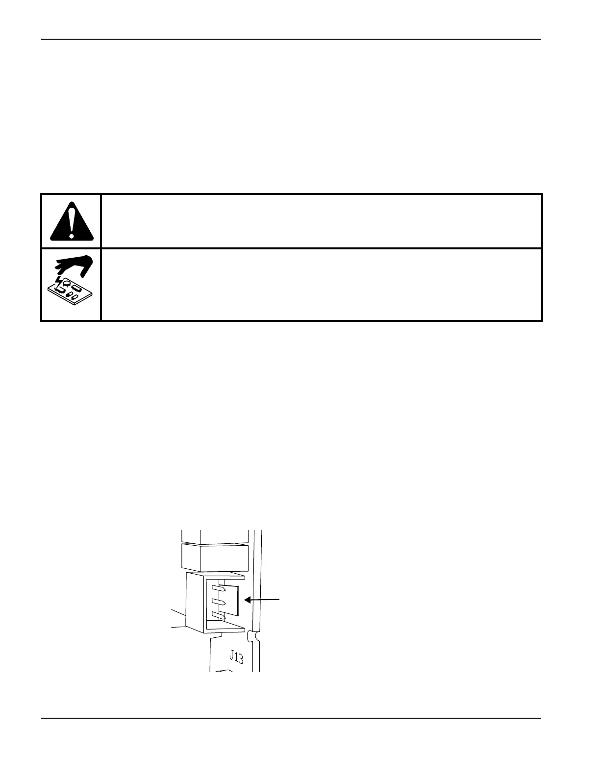
3. Remove the TORCH START connector (J12) on the component side of the power board by pushing the tab on the
connector toward the plug and pulling the plug out.
Figure 47
Kit number Description
428402 Kit: Power board, CSA (141351)
428403 Kit: Power board, CE (141357)
CAUTION!
Static electricity can damage circuit boards. Use proper precautions when handling
printed circuit boards.
Store PC boards in anti-static containers.
Wear a grounded wrist strap when handling PC boards.

 Loading...


