EasyManuals Logo

Hypertherm Powermax30 AIR Service Manual

Hypertherm Powermax30 AIR
223 pages
To Next Page IconTo Next Page
To Previous Page IconTo Previous Page
Page #127 background imageLoading...
Page #127 background image
Powermax30 AIR Service Manual 808850 127
6 Power Supply Component Replacement
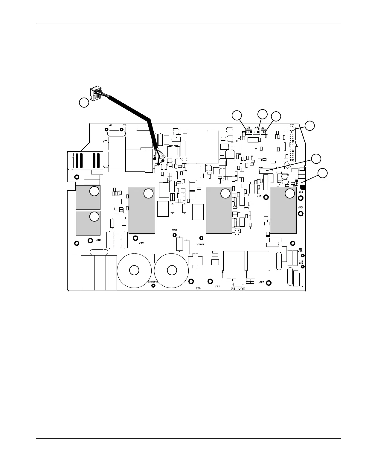
4. Remove the connectors at J5, J6, and J9 on the component side of the power board.
5. Remove the J3 connector from the compressor-driver board.
Figure 48
1
2
4
7
8
9
1
3 3 3
2
5
6
10
1
Input diode bridges
2
Capacitors
3
IGBTs
4
J12 (TORCH START connector)
5
Snubber resistor
6
J7 (ribbon cable connector)
7
J9
8
J6
9
J5
10
J3 (connects to compressor-driver board)

Table of Contents

Other manuals for Hypertherm Powermax30 AIR

Questions and Answers:

Question and Answer IconNeed help?

Do you have a question about the Hypertherm Powermax30 AIR and is the answer not in the manual?

Hypertherm Powermax30 AIR Specifications

General IconGeneral
Built-in Air CompressorYes
Output Voltage83 VDC
Input Voltage120-240 V
Current Output15–30 A
Cutting ThicknessUp to 10 mm (3/8 in) recommended cut
Gas SupplyBuilt-in air compressor
Operating Temperature-10°C to +40°C (+14°F to +104°F)

Related product manuals