84 Powermax30 AIR Service Manual 808850
5 – Troubleshooting and System Tests
Test 4 – solenoid valve
This test verifies the proper operation of the solenoid valve (V1).
1. Set the power switch to OFF (O), and disconnect the power cord from the power source.
2. Remove the power supply handle and cover. See Remove the power supply cover on page 98.
3. Remove the component barrier. See Remove the component barrier on page 100.
4. Reconnect the electrical power.
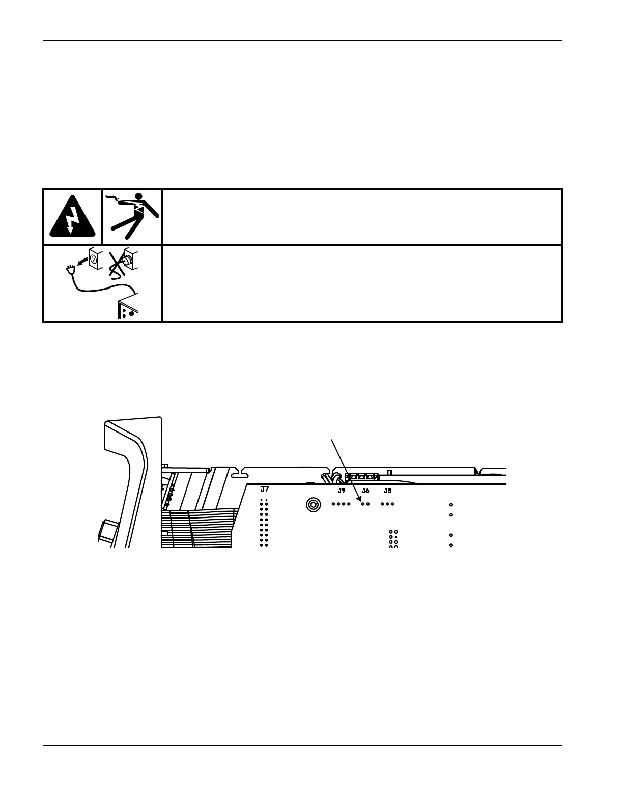
5. Place a jumper from pin 1 of J6 (red wire) on the power board to ground. See Figure 5 on page 73 for grounding
options.
Figure 14
6. Turn the power ON (I). The valve should click.
7. Measure the voltage between pin 1 of J6 and ground.
8. If you do not hear the valve click and the voltage check reads 24 VDC, replace the solenoid valve. See Replace the
solenoid valve on page 142.
WARNING!
ELECTRIC SHOCK CAN KILL
Use extreme caution when working near live electrical circuits. Dangerous
voltages exist inside the power supply that can cause serious injury or death.
See the WARNING! on page 57 before proceeding.