EasyManuals Logo

Hypertherm Powermax30 AIR Service Manual

Hypertherm Powermax30 AIR
223 pages
To Next Page IconTo Next Page
To Previous Page IconTo Previous Page
Page #103 background imageLoading...
Page #103 background image
Powermax30 AIR Service Manual 808850 103
6 Power Supply Component Replacement
Figure 27
Reattach the front panel
1. Push the front panel into the base of the power supply until it snaps into place.
2. Tighten the retaining screw to 23.0 kg∙cm (20 inch∙pounds). See Figure 26 on page 102.
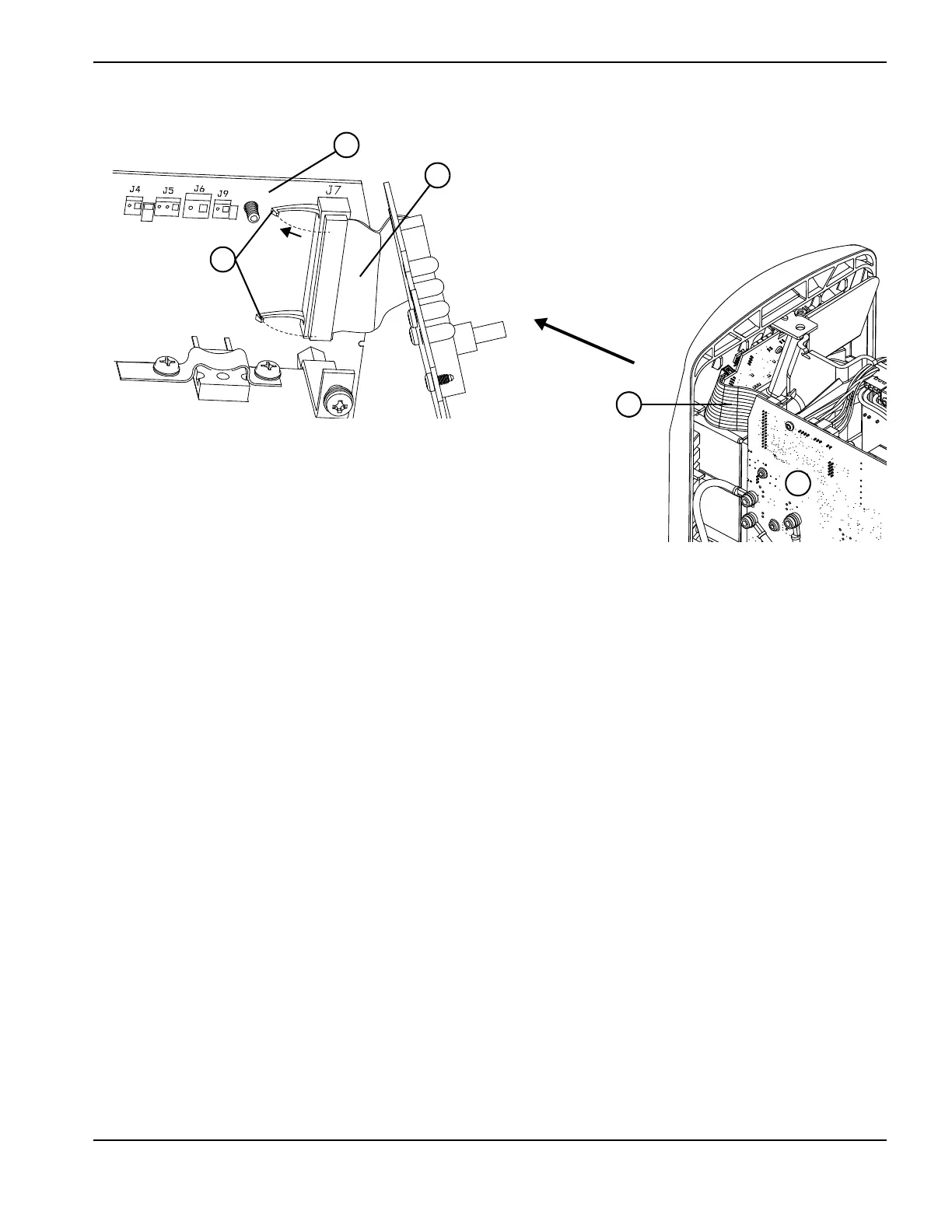
3. Reconnect the control board’s ribbon cable to the power board at J7. Make sure the latches are folded up to hold the
connector in place.
4. Tighten the strain relief nuts on the torch lead and work lead.
5. Put the power supply cover back in place. See Install the power supply cover on page 99.
6
6
7
8
7

Table of Contents

Other manuals for Hypertherm Powermax30 AIR

Questions and Answers:

Question and Answer IconNeed help?

Do you have a question about the Hypertherm Powermax30 AIR and is the answer not in the manual?

Hypertherm Powermax30 AIR Specifications

General IconGeneral
Built-in Air CompressorYes
Output Voltage83 VDC
Input Voltage120-240 V
Current Output15–30 A
Cutting ThicknessUp to 10 mm (3/8 in) recommended cut
Gas SupplyBuilt-in air compressor
Operating Temperature-10°C to +40°C (+14°F to +104°F)

Related product manuals