178 Powermax30 AIR Service Manual 808850
6 – Power Supply Component Replacement
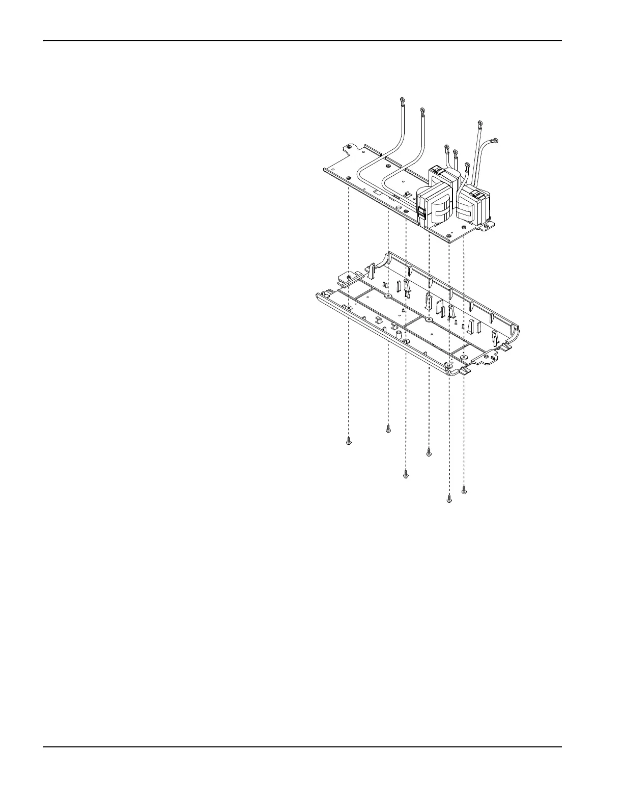
Install the magnetics assembly
1. Align the screw holes in the plastic base
with the screw holes in the metal plate on
the bottom of the new magnetics assembly.
2. Attach the new magnetics to the plastic
base using the 6 screws. Tighten the
screws to 23.0 kg·cm (20 inch·pounds).
3. Align the wires from the magnetics with the
notches at the bottom of the center panel
so that the wires do not get pinched.
4. Press the plastic base and the magnetics
into the bottom of the power supply until the
assembly snaps into place.
5. On the fan side of the power supply, attach
the ring terminal for the output inductor’s
white wire to the stud labeled “WHT” using
an 8 mm (5/16 inch) nut driver. Tighten the
nut to 23.0 kg·cm (20 inch·pounds). See
Figure 87 on page 176.
Also put back in place any other wires
you removed from the “WHT” stud.
6. Using the screw you removed in step 3 on
page 176, attach the ground wire to the
metal base plate of the magnetics assembly.
Tighten the screw to 17.3 kg∙cm
(15 inch∙pounds).

 Loading...


