EasyManuals Logo

Hypertherm Powermax30 AIR Service Manual

Hypertherm Powermax30 AIR
223 pages
To Next Page IconTo Next Page
To Previous Page IconTo Previous Page
Page #179 background imageLoading...
Page #179 background image
Powermax30 AIR Service Manual 808850 179
6 Power Supply Component Replacement
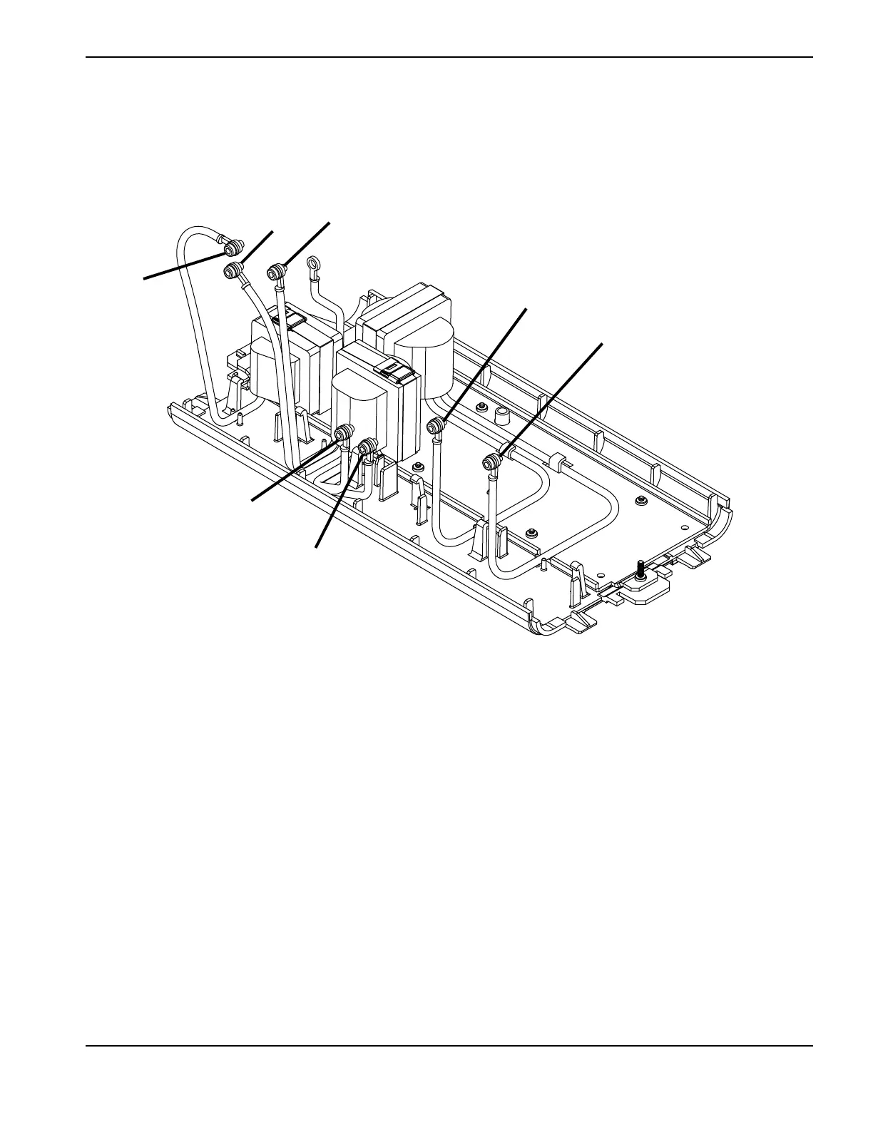
7. On the power board side of the power supply, connect the wires for the transformers and inductors on the new
magnetics assembly to the power board at J13, J14, J15, J18, J19, J20, and J21. Tighten each screw to 23.0 kg∙cm
(20 inch∙pounds).
Figure 89
8. Complete the following procedures:
a. See Install the internal compressor on page 163.
b. See Install the heat exchange coil on page 158.
c. See Install the fan on page 156.
d. See Reattach the rear panel on page 106.
e. See Reattach the front panel on page 103.
f. See Install the component barrier on page 101.
g. See Install the power supply cover on page 99.
h. Reconnect the power cord, and set the power switch to ON (I).
J13
J14
J15
J21
J20
J19
J18

Table of Contents

Other manuals for Hypertherm Powermax30 AIR

Questions and Answers:

Question and Answer IconNeed help?

Do you have a question about the Hypertherm Powermax30 AIR and is the answer not in the manual?

Hypertherm Powermax30 AIR Specifications

General IconGeneral
Built-in Air CompressorYes
Output Voltage83 VDC
Input Voltage120-240 V
Current Output15–30 A
Cutting ThicknessUp to 10 mm (3/8 in) recommended cut
Gas SupplyBuilt-in air compressor
Operating Temperature-10°C to +40°C (+14°F to +104°F)

Related product manuals