EasyManuals Logo

Hypertherm Powermax30 AIR Service Manual

Hypertherm Powermax30 AIR
223 pages
To Next Page IconTo Next Page
To Previous Page IconTo Previous Page
Page #101 background imageLoading...
Page #101 background image
Powermax30 AIR Service Manual 808850 101
6 Power Supply Component Replacement
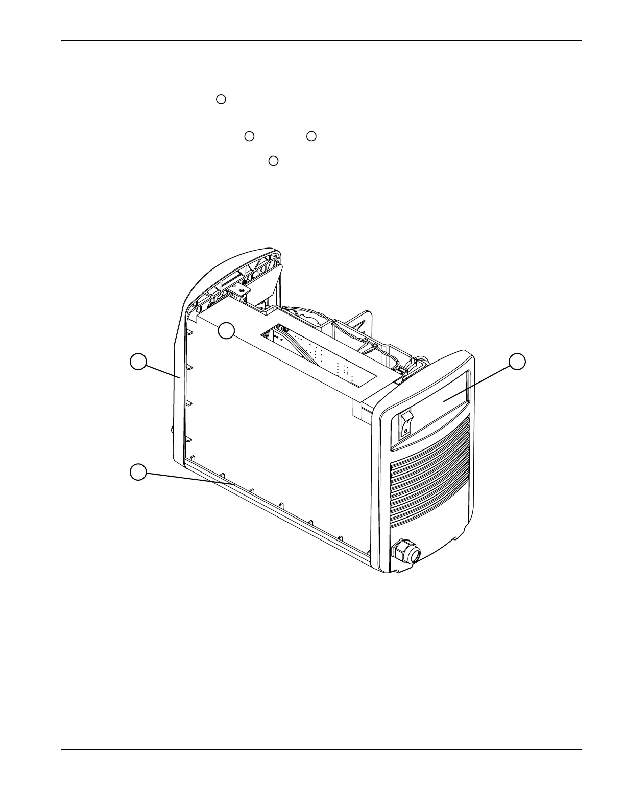
Install the component barrier
1. Position the component barrier so that the folded top edge will cover the top of the power board.
2. As you slide the barrier into place, tuck the sides and the bottom edge of the barrier behind the plastic notches that
run along the inside of the front panel , rear panel , and plastic base.
The barrier will not fit in the same track as the power supply cover.
3. Put the power supply cover back in place. See Install the power supply cover on page 99.
Figure 25
1
2
3
4
1
2 3
4

Table of Contents

Other manuals for Hypertherm Powermax30 AIR

Questions and Answers:

Question and Answer IconNeed help?

Do you have a question about the Hypertherm Powermax30 AIR and is the answer not in the manual?

Hypertherm Powermax30 AIR Specifications

General IconGeneral
Built-in Air CompressorYes
Output Voltage83 VDC
Input Voltage120-240 V
Current Output15–30 A
Cutting ThicknessUp to 10 mm (3/8 in) recommended cut
Gas SupplyBuilt-in air compressor
Operating Temperature-10°C to +40°C (+14°F to +104°F)

Related product manuals