156 Powermax30 AIR Service Manual 808850
6 – Power Supply Component Replacement
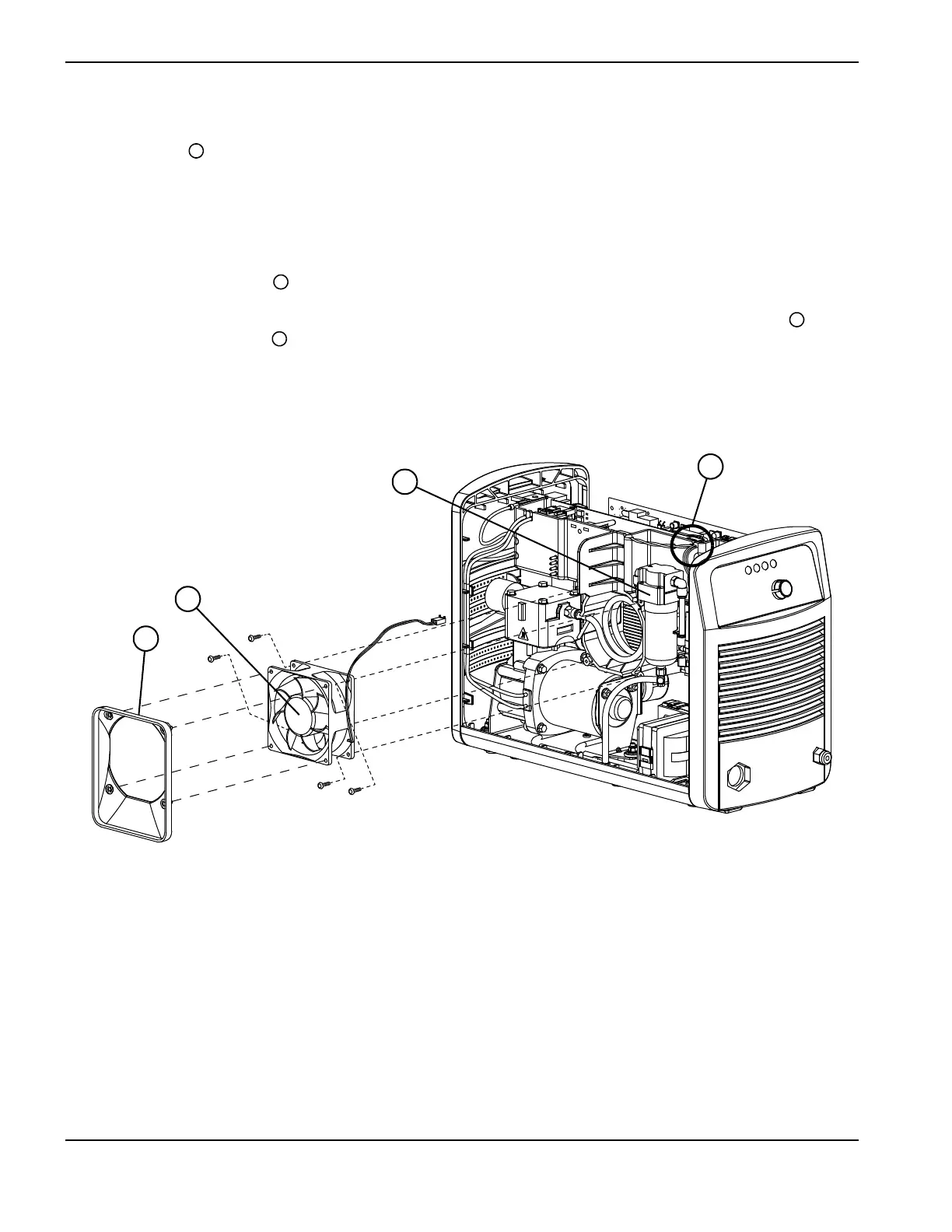
Install the fan
1. Orient the fan so that the red-and-black wires extend from the bottom-right corner of the fan (the side closest to
the front panel).
2. Loosely install the 4 retaining screws. Use the screws included in the kit if needed.
3. Once all 4 retaining screws are installed, tighten them to 11.5 kg∙cm (10 inch∙pounds).
4. Orient the new fan plenum so that the wider end is at the bottom, and snap it onto the fan. See Figure 70.
5. Route the fan’s red-and-black wires through the notch in the top of the center panel that is labeled “FAN” . The
notch is above the air filter .
6. Attach the connector for the red-and-black wires to J5 on the power board.
Figure 70
7. Complete the following procedures:
a. See Install the power supply cover on page 99.
b. Reconnect the power cord, and set the power switch to ON (I).

 Loading...


