EasyManuals Logo

Hypertherm Powermax30 AIR Service Manual

Hypertherm Powermax30 AIR
223 pages
To Next Page IconTo Next Page
To Previous Page IconTo Previous Page
Page #176 background imageLoading...
Page #176 background image
176 Powermax30 AIR Service Manual 808850
6 Power Supply Component Replacement
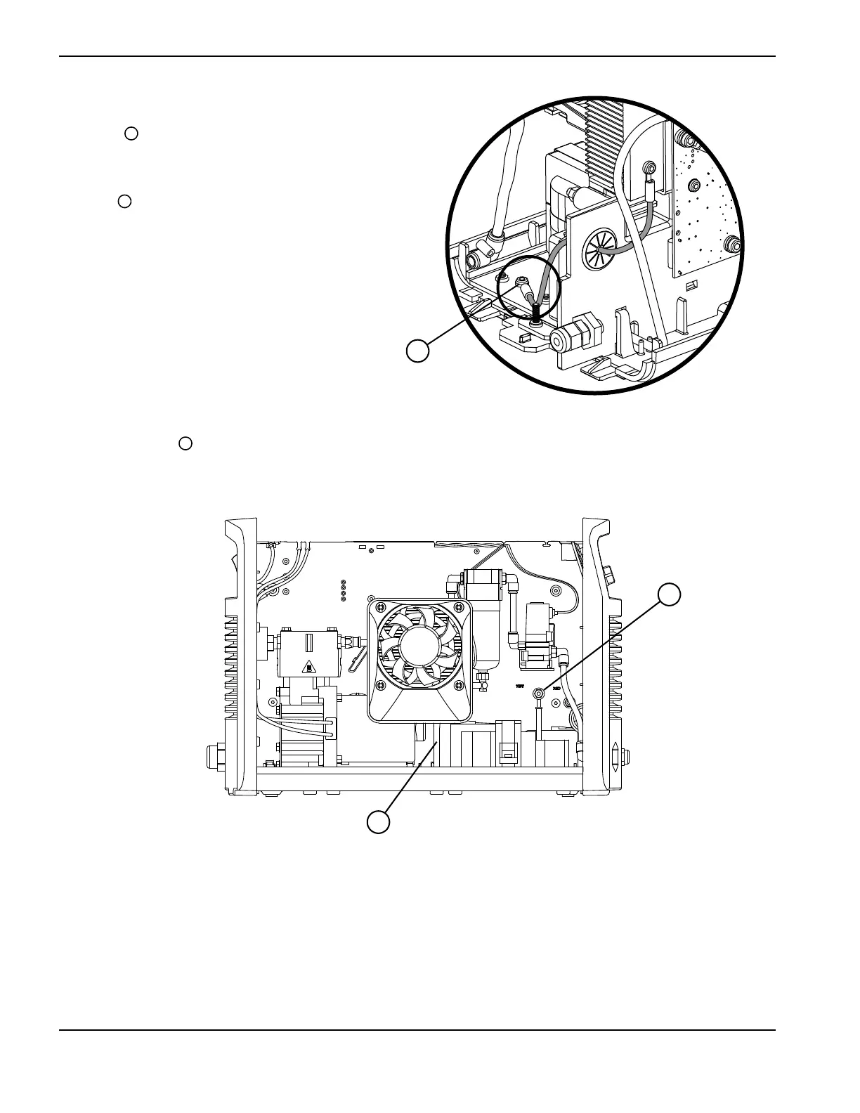
3. On the fan side of the power
supply, remove the ground wire
screw from the base of the
magnetics assembly.
4. Make sure the air filters drain
hose is disconnected from the
hole in the bottom of the base.
It is normal to see water in the
drain hose and in the air filter
bowl. Remove any water that
spills inside the power supply
before operating the system
again.
5. Use an 8 mm (5/16 inch) nut driver
to remove the nut that attaches the
ring terminal for the output
inductors white wire to the stud
labeled “WHT” .
Figure 87
1
1
2
3
2
3

Table of Contents

Other manuals for Hypertherm Powermax30 AIR

Questions and Answers:

Question and Answer IconNeed help?

Do you have a question about the Hypertherm Powermax30 AIR and is the answer not in the manual?

Hypertherm Powermax30 AIR Specifications

General IconGeneral
Built-in Air CompressorYes
Output Voltage83 VDC
Input Voltage120-240 V
Current Output15–30 A
Cutting ThicknessUp to 10 mm (3/8 in) recommended cut
Gas SupplyBuilt-in air compressor
Operating Temperature-10°C to +40°C (+14°F to +104°F)

Related product manuals