EasyManuals Logo

Hypertherm Powermax30 AIR Service Manual

Hypertherm Powermax30 AIR
223 pages
To Next Page IconTo Next Page
To Previous Page IconTo Previous Page
Page #111 background imageLoading...
Page #111 background image
Powermax30 AIR Service Manual 808850 111
6 Power Supply Component Replacement
CE power cords
1. Complete the following procedures:
a. Set the power switch to OFF (O), and disconnect the power cord from the power source.
b. See Remove the power supply cover on page 98.
c. See Remove the component barrier on page 100.
d. See Detach the rear panel on page 104.
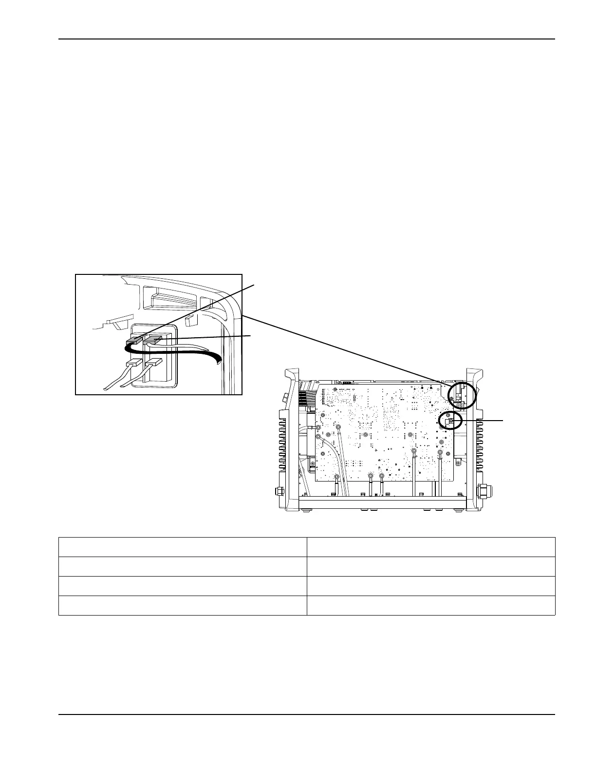
CE power cords have a brown wire and a blue wire that connect to the power switch and
a green/yellow ground wire that connects to the heatsink.
2. Remove the blue and brown wires from the power switch.
Figure 34 – Single-phase CE power cord wires
Designator Wire color
L (live) Brown
N (neutral) Blue
PE (ground) Green/yellow
AC AC
N
L
PE

Table of Contents

Other manuals for Hypertherm Powermax30 AIR

Questions and Answers:

Question and Answer IconNeed help?

Do you have a question about the Hypertherm Powermax30 AIR and is the answer not in the manual?

Hypertherm Powermax30 AIR Specifications

General IconGeneral
Built-in Air CompressorYes
Output Voltage83 VDC
Input Voltage120-240 V
Current Output15–30 A
Cutting ThicknessUp to 10 mm (3/8 in) recommended cut
Gas SupplyBuilt-in air compressor
Operating Temperature-10°C to +40°C (+14°F to +104°F)

Related product manuals