Powermax30 AIR Service Manual 808850 117
6 – Power Supply Component Replacement
Install the power switch
1. Press the new power switch into the rear panel with the ON (I) label at the top of the switch.
You should hear the switch snap into place.
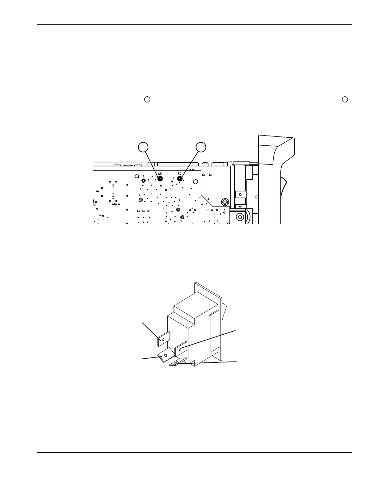
2. Press the connectors for the 2 white wires that are attached to the power board at “AC” onto the bottom 2 pins of
the power switch. The left “AC” wire connects to the bottom-left pin on the power switch; the right “AC” wire
connects to the bottom-right pin on the power switch. See Figure 38 and Figure 39.
Figure 38
3. Press the connector for the black (CSA) or brown (CE) wire onto the upper-left pin on the power switch.
4. Press the connector for the white (CSA) or blue (CE) wire onto the upper-right pin on the power switch.
Figure 39
5. Complete the following procedures:
a. See Install the component barrier on page 101.
b. See Install the power supply cover on page 99.
c. Reconnect the power cord, and set the power switch to ON (I).
White (AC) (bottom-left pin)
Black (CSA)
Brown (CE)
(upper-left pin)
White (AC) (bottom-right pin)
White (CSA)
Blue (CE)
(upper-right pin)

 Loading...


