- 7 -
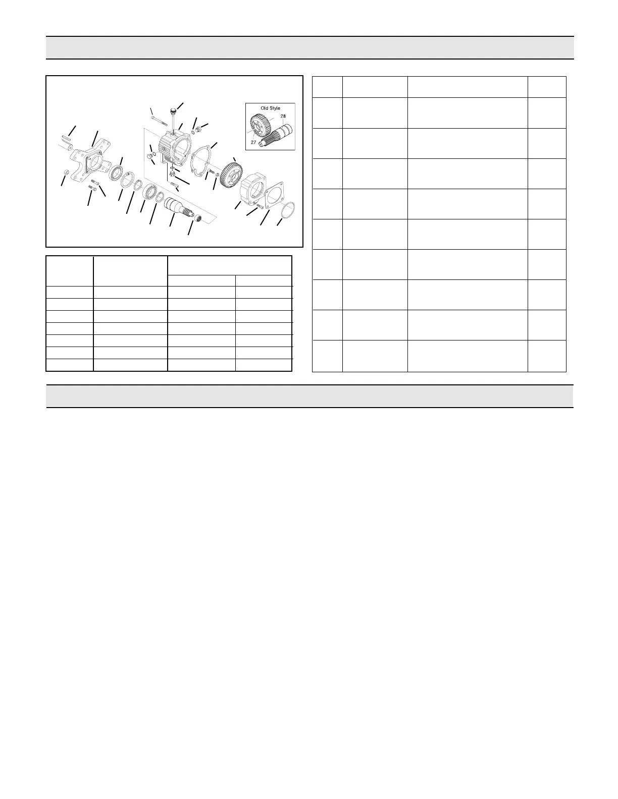
Parts List for Gear Reduction Kit 9910-KIT1642
Gear Reduction Kit 9910-KIT1642 Installation
Ref. No. Description Tightening Torque
In. Lbs. Nm
2 Bolt 218.7 24.5
7 Bolt 171.4 19.6
9 Plug 171.4 19.6
11 Bolt 218.7 24.5
12 Bolt 218.7 24.5
19 Bolt 218.7 24.5
20 Bolt 218.7 24.5
REF. PART QTY.
NO. NUMBER DESCRIPTION REQÕD.
1 9910-620561 O-Ring 1
2 9910-180030 M8x20 Bolt 1
3 9910-621000 Pump Adapter Flange 1
4 9910-620990 Bearing 1
5 9910-651620 Gear 1
6 9910-200231 Lock Washer 6
7 9910-160671 Bolt 1" Long 3
8 9910-620960 Gearbox Body 1
9 2406-0023 Plug 3
10 9910-740290 O-Ring 3
11 9910-540290 M8x25 Bolt 4
12 9910-621010 M10x75 Bolt 4
13 9910-1140370 Dipstick 1
14 9910-651610 Pinion Gear 1
15 9910-320240 Retaining Ring (Ext.) 2
16 9910-961780 Bearing 1
17 9910-961790 Retaining Ring (Int.) 1
18 9910-961800 Seal 1
19 9910-651000 Bolt 4
20 9910-961900 Bolt 4
21 9910-1320940 Engine Adapter Flange 1
22 9910-961770 Spacer 4
23 9910-650990 Key 1
24 9910-620950 Gasket 1
25 9910-650270 Gasket 1
27 9910-620980 Gear 1
28 9910-650400 Pinion Gear 1
4
2
1
3
5
6
7
10
9
11
24
9
10
8
13
12
23
22
21
10
9
14
15
16
15
17
18
19
20
25
Form L-1383 (12/11, Rev. B)
NOTE:
¥ Use support for all pumps that weigh 25 lbs. or more.
¥
Use Loctite 242 - Thread Locker, or equivalent, for
complete assembly.
¥ The following reference numbers refer to the gearbox
illustration above.
The 9910-KIT1642 gear reducer was designed for direct
mounting the 9910-D813, -D1064 and -D1265 onto
8 - 18 hp gas engines with flange mount and 1" solid
shafts.
1. On the 9910-D813, -D1064 and -D1265, the square
metal plate must be removed from the shaft side of the
pump. Lubricate the o-ring (Ref. 1) in the pump
adapter flange (Ref. 3). Slip the flange over machined
surface of casting of the brass spacer ring installed on
the shaft of all the 9910-D813,-D1064 and -D1265
pumps.
2. Install the pump gear (Ref. 5) with pilot diameter of
gear inserted into the inner-diameter of the pump
shaft. Secure firmly onto the shaft using 10x25 mm
allen head bolts (Ref. 7) and lock washers (Ref. 6).
3. Align holes in pump adapter flange (Ref. 3) with
threaded holes in the pump body. Lubricate the gasket
(Ref. 24) and place in position on gearbox body (Ref.
8). Install the gearbox body (Ref. 8) on the pump
adapter flange (Ref. 3) and secure firmly with 10x75
mm allen head bolts (Ref. 12). Install the 8 x 20 mm
allen head bolt (Ref. 2) and securely tighten.
4. Install the engine flange adapter (Ref. 21) raised side
out to engine boss, using 5/16"x1"x 24 N.F. allen head
bolts (Ref. 19). Lock firmly into place.
5. Insert the long key (Ref. 23) into engine shaft keyway.
Align the keyway in the gear reducer input shaft
(Ref. 14) and slide the pump and gear reducer onto
the engine shaft.
6. Align the holes in gearbox body (Ref. 8) with the
threaded holes in the engine flange adapter (Ref. 21).
Insert the 8x25 mm allen head bolts (Ref. 11) through
the gearbox body (Ref. 8) and thread into the engine
flange adapter (Ref. 21). Securely tighten with the
allen wrench provided.
7. Dipstick (Ref. 13) must always be installed or re-
installed in the uppermost threaded hole of the
gearbox body (Ref. 8). Both the plugs (Ref. 9) and
dipstick (Ref. 13) are all interchangeable for gear
reduction mounting convenience.
8. Fill the gear case with 90W gear lube. To properly fill,
first tighten the bottom drain plug (Ref. 9); second,
remove the side level plug (Ref. 9) and the dipstick
(Ref. 13). Fill until the gear lube is no higher than the
mark on the dipstick.
9. Replace and tighten the side level plug and the
dipstick.
 Loading...