D0360 REV. I ©2018 SMART DC INSTALLATION INSTRUCTIONS www.hysecurity.com | 5
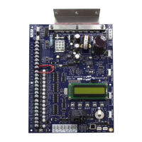
ASSESS YOUR GATE SITE. UL 325-
2016 COMPLIANCE
Review your gate installation. Entrapment
zones should be kept to a minimum.
Three inputs are available on the Controller
for monitoring external entrapment protection
sensors. Set Build Year according to your gate
manufacturing date. See "Setting the Build Year"
on page 6.
Figure 5. Site Overview
WHEN BY ≥ 2, INSTALL NC
SENSORS.
Install contact and/or non-contact
sensors (edge sensors and photo eyes)
for all entrapment zones. HySecurity gates monitor
normally closed (NC) sensors. Wire your NC
sensors to SENSOR input terminals (SENSOR 1,
SENSOR 2, or SENSOR 3) on Smart DC Controllers.
1
opening
ENTRAPMENT
6 ft (1.8 m) minimum
WARNING
ZONE
Photo eye thru-beam
protecting Trailing End
(EYE OPEN)
Photo eye
thru-beam
protecting
Leading End
(EYE CLOSE)
2
CAUTION
All external entrapment protection sensors
must be wired to the SENSOR COM terminal
for power and monitoring purposes. The
three SENSOR inputs are interchangeable and
congurable. For example, it doesn’t matter
whether you wire a normally closed photo
eye sensor or edge sensor to the SENSOR
1, 2, or 3 input. However, due to monitoring
requirements, each SENSOR input (1, 2, and
3) can only accept one NC sensor output
connection.
Table 3. Menu Mode Navigation
Change
Displayed
Data
Navigate
Selections
Choose
Displayed
Data
Navigate
Menu Items
Press
Select.
Two left
characters
blink.
Press Next
or Previous.
Continue
pressing
Next to
view all
selections.
Press
Select.
Blinking
characters
become
static.
Press Next
to Advance
Press
Previous to
Previous.
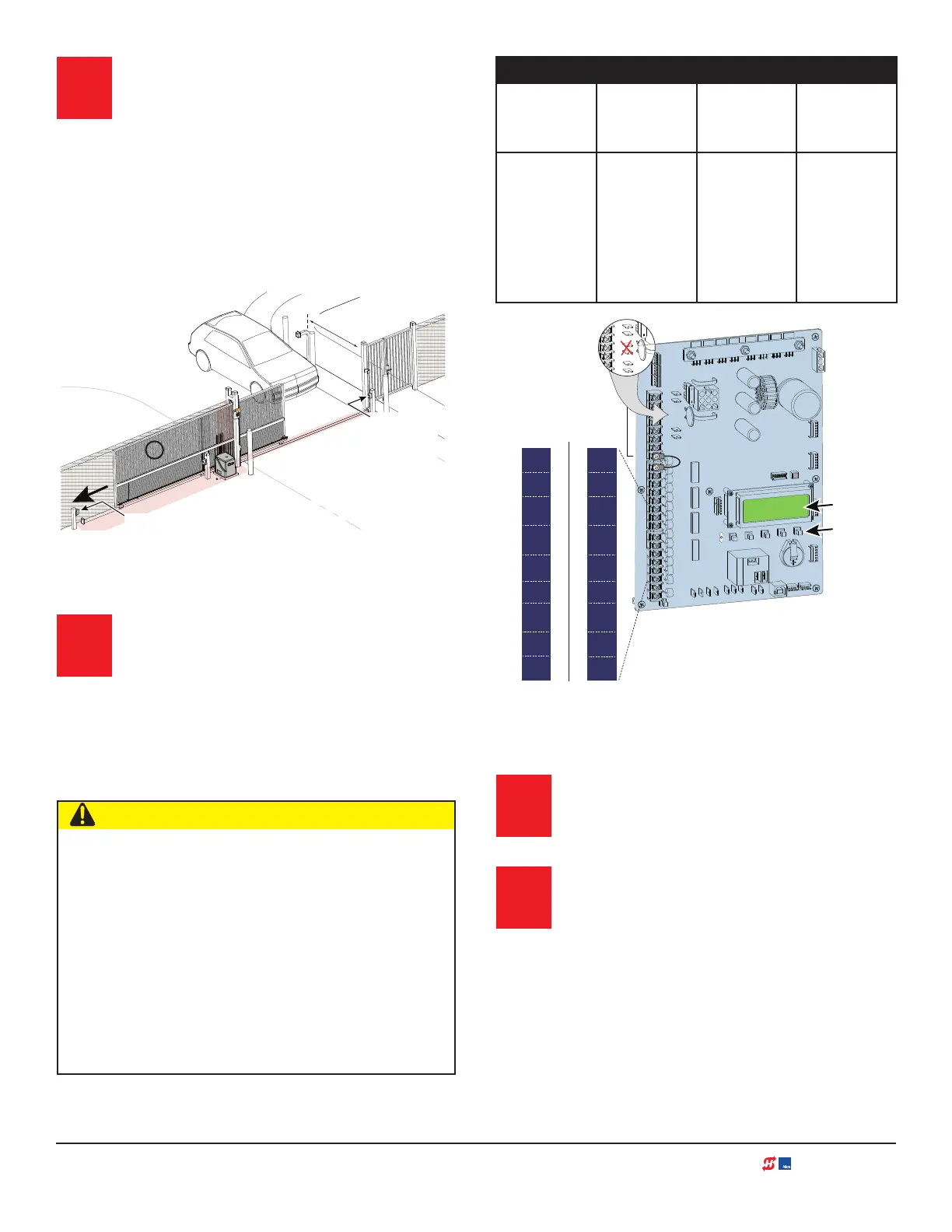
Figure 6. SDC Board BY-Lable Changes
TURN POWER ON.
See Figure 3.
ANSWER INITIAL SETUP PROMPTS.
Answer the prompts. When you enter
Operator Type, access the next prompt
by pressing Next. Enter the Build Year
based on the date the gate was manufactured.
Each SENSOR input whether or not it has
a sensor wired to it, must be programmed
before the gate will move.
COM
COM
COM
COM
COM
COM
COM
COM
STOP
OPEN
RADIO
CLOSE
OPEN
OPEN
PARTIAL
SENSOR 2
EXIT
LOOP
BLOCK
EXIT
IN OBS
LOOP
OUT OBS
LOOP
CENTER
LOOP
SENSOR 1
SENSOR
COM
+ 24 V
EMERG
OPEN
SHOW
LEDs
R
AD
I
O
OP
T
I
ON
S
S
1
+
2
4
V
O
P
E
N
C
O
M
D
U
A
L
G
A
T
E
C
O
M
B
A
U
S
E
R
2
C
O
M
N
O
D
C
COMMON
TERMINALS
USER RELAY 1
Electro-mechanical
24VDC
24VDC
12VDC
12VDC
24VDC
24VDC
24VAC
24VAC
12VDC
12VDC
R
S
-48
5
U
S
B
SENSOR 3
SENSOR 2
SENSOR 3
SENSOR 1
SENSOR
COM
EXIT
LOOP
BLOCK
EXIT
CENTER
LOOP
IN OBS
LOOP
OUT OBS
LOOP
EXIT
LOOP
CENTER
LOOP
EYE
CLOSE
EYE
OPEN
EDGE
EYE
COM
BLOCK
EXIT
IN OBS
LOOP
OUT OBS
LOOP
Pre-2016
Build Year (BY 1)
MX3978-02
Post 2016 Label
Build Year (BY 2)
MX3978-01
Labels are
available and
may be overlaid
to cover the silk
screened text
on the controller
inputs.
SMART DC
DISPLAY
KEYPAD
3
4