NOTE: ONCE THE VALVE ROCKER ARM ASSEM-
BLIES ARE INSTALLED AND PROPERLY TOR-
QUED, NO ADDITIONAL VALVE LASH ADJUST-
MENT IS REQUIRED.
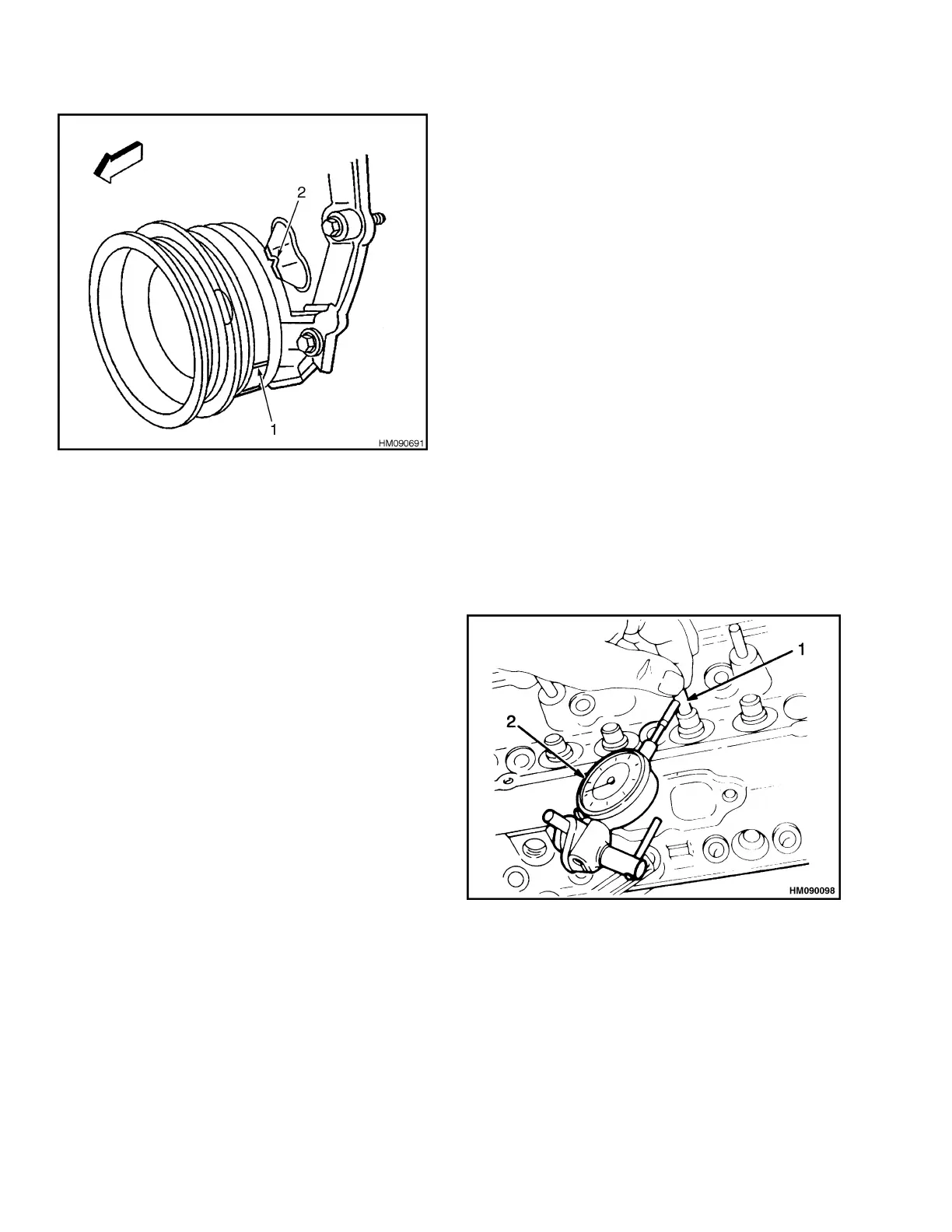
1. CRANKSHAFT BALANCER ALIGNMENT MARK
2. ENGINE FRONT COVER ALIGNMENT TAB
Figure 13. Rotate Crankshaft Balancer
5.
Tighten valve rocker arm bolts to 30 N•m (22
lbf ft). See Figure 19. Repeat for other side.
6.
Use new gasket and install rocker covers. In-
stall new grommets on capscrews and install
capscrews into rocker covers. Tighten cap-
screws to 12 N•m (107 lbf in). See Figure 22.
Repeat for other side.
7.
Install air inlet hose on PCV valve. Tighten
clamp.
8.
Install each spark plug wire shield and spark
plugs.
9.
Install spark plug wires to their appropriate
spark plugs.
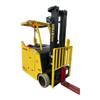
VALVE GUIDES AND SEATS, REPAIRS
Measure clearance between valve stem and guide
as follows:
1.
Clamp a dial indicator on exhaust port side
of the cylinder head. See Figure 14.
2.
Position dial indicator so that movement of
valve stem from side to side, crosswise to cyl-
inder head, will cause a direct movement of
dial indicator stem.
The dial indicator stem must contact side of
valve stem just above valve guide.
3.
Lower valve head about 1.6 mm (0.063 in.)
below valve seat.
4.
Using light pressure, move valve stem from
side to side in order to obtain valve stem-to-
guide clearance reading.
See Engine Specifications for maximum clearances.
If clearance is more than maximum amount, over-
size valves or new valve guides must be installed.
Use a reamer of correct size when installing new
valve guides. Use normal service procedures when
grinding valve seats. See Engine Specifications for
dimensions.
1. VALVE STEM
2. DIAL INDICATOR
Figure 14. Valve Steam Clearance
Cylinder Head Repair 0600 SRM 1251
10