11
When air is added to the tires, use a remote air chuck.
The person adding air must stand away and to the
side and not in front of the tire.
Keep the tires at the correct air pressure. (See the Name-
plate.) Check the air pressure with a gauge when the
tires are cold. If it is necessary to add air to a tire that is
warm, check one of the other tires on the same axle and
add air to the tire that has low pressure so that the air
pressures are equal. The air pressure of the warm tires
must always be equal to or greater than the specification
for air pressure for cold tires.
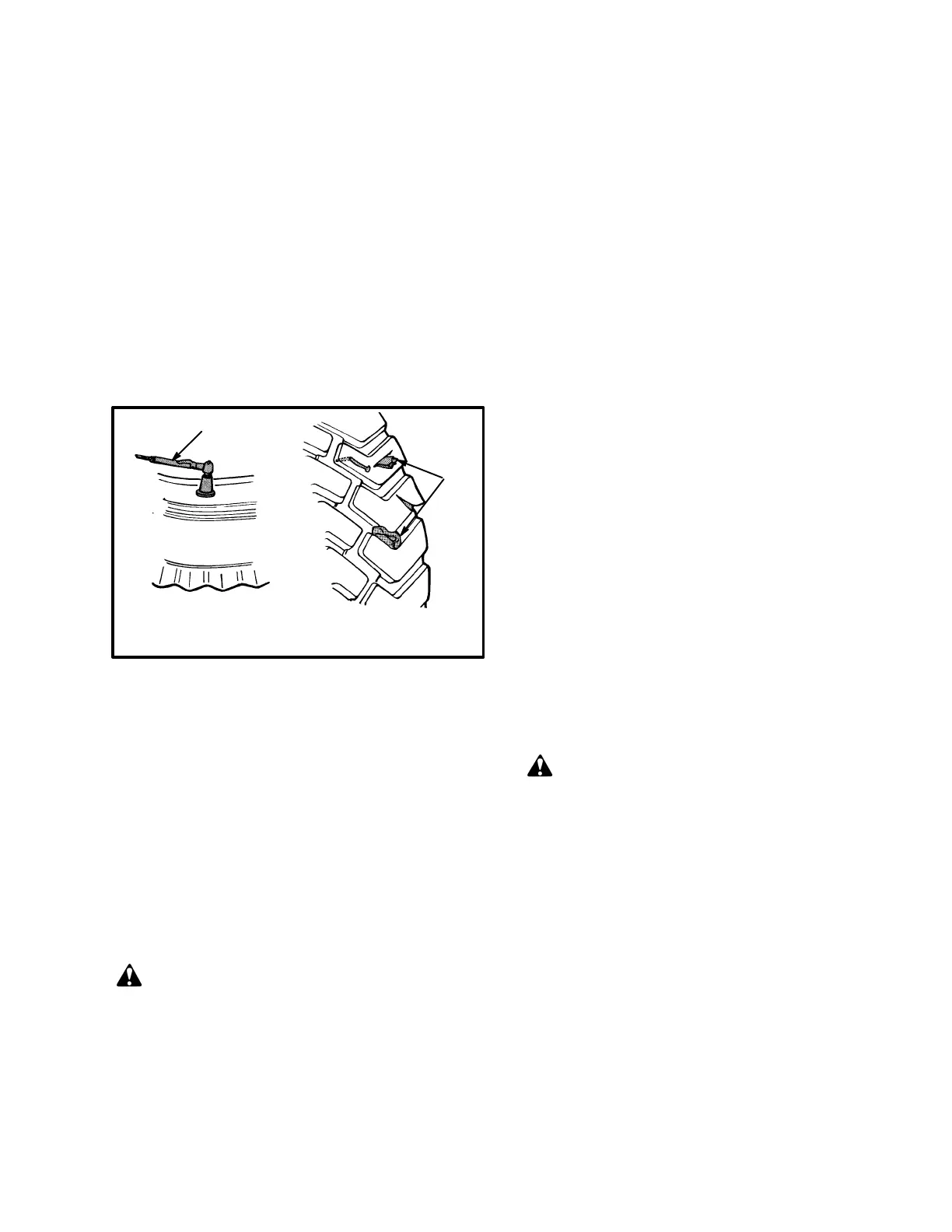
1. CHECK THE TIRE PRESSURE
2. CHECK FOR DAMAGE
9447
FIGURE 10. CHECK THE TIRES
1
2
Check the tires for damage. Check the tread and remove
any objects that will cause damage. Check for bent or
damaged rims. Check for loose or missing parts. Re-
move any wire, straps or other material wrapped around
the axle.
Make sure the drive wheel nuts are tight. Tighten the
wheel nuts in a cross pattern to the correct torque value
shown in the MAINTENANCE SCHEDULE.
CAUTION
When the drive wheels have been installed check all
wheel nuts after 2 to 5 hours of operation. Tighten
the nuts in a cross pattern to the correct torque value
shown in the MAINTENANCE SCHEDULE. When
the nuts stay tight for eight hours, the interval for
checking the torque can be extended to 350 hours.
Forks
The identification of a fork is how the fork is connected
to the carriage. The H3.50–5.00XL (H70–110XL) se-
ries of lift trucks can have either a hook fork or a pin
fork. The H6.00–7.00XL (H135–155XL) series of lift
trucks normally have a pin fork. See FIGURE 13.
Forks, Adjustment
Hook forks are connected to the carriage by hooks and
lock pins. See FIGURE 12. These lock pins are installed
through the top fork hooks and fit into slots in the top
carriage bar. Adjust the forks as far apart as possible for
maximum support of the load. Hook forks will slide
along the carriage bars to adjust for the load to be lifted.
Raise the lock pin in each fork to slide the fork on the
carriage bar. Make sure the lock pin is engaged in the
carriage bar to lock the fork in position after the width
adjustment is made.
Pin forks are fastened to the carriage with large fork
pins. A lock pin for each fork fits into the top carriage
bar and a slot in the fork. These lock pins hold the fork in
position. See FIGURE 13. Adjust the forks as far apart
as possible for maximum support of the load. Make sure
the lock pin is engaged in the carriage bar and the fork.
The fork must be locked into position after the adjust-
ment is made.
Forks, Removal And Installation
WARNING
Do not try to move a fork without a lifting device.
Each fork for these lift trucks can weigh (66 kg to 183
kg [145 to 402 lb] for a hook fork) and (128 to 226 kg
[281 to 498 lb] for a pin fork).
A fork can be removed from the carriage for replace-
ment of the fork or other maintenance.
Hook Fork (Removal). Slide a hook fork to the fork re-
moval notch on the carriage. See FIGURE 12. Lower
the fork onto blocks so that the bottom hook of the fork
moves through the fork removal notch. See
FIGURE 11. Lower the carriage further so that the top
hook of the fork is disengaged from the top carriage bar.
Move the carriage away from the fork, or use a lifting
device to move the fork away from the carriage.