12
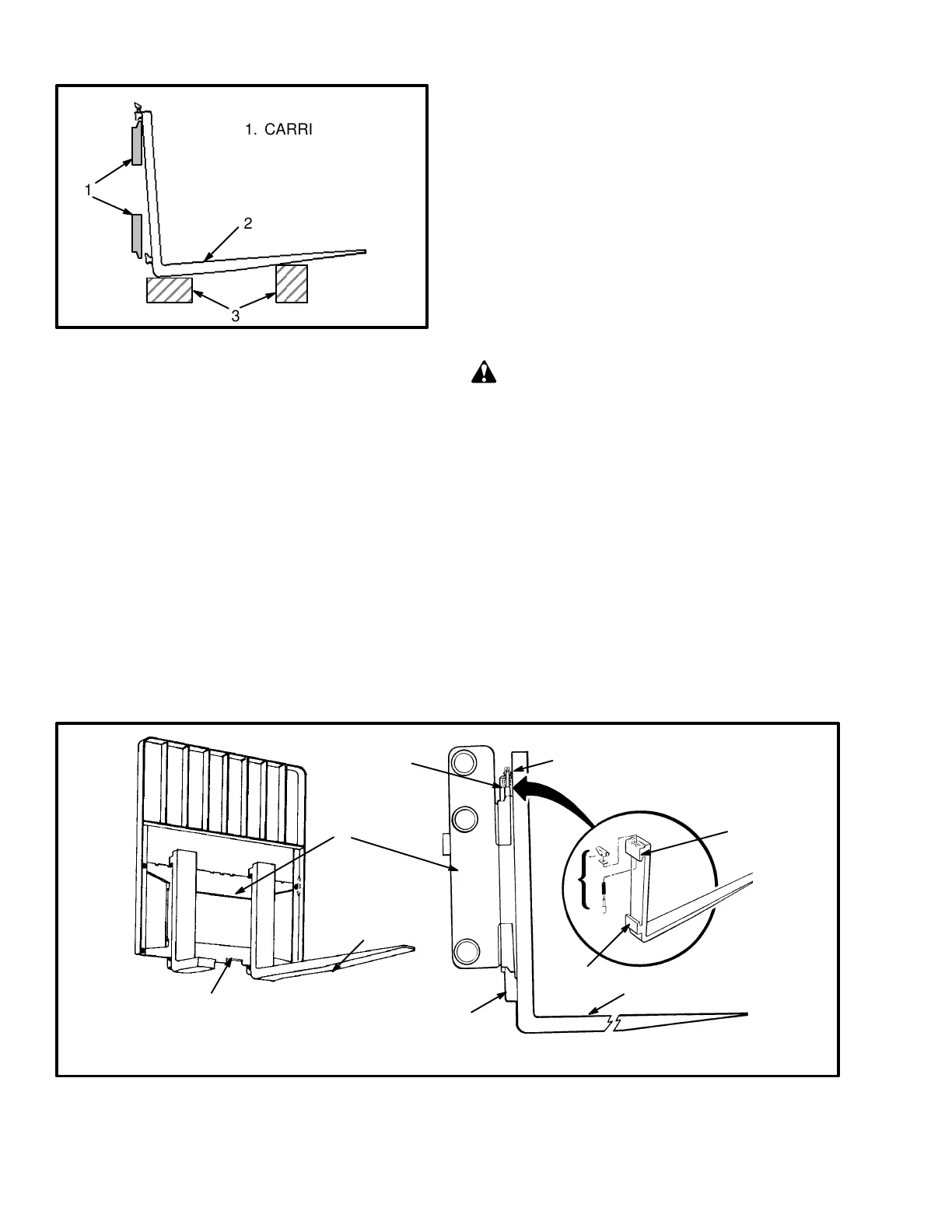
FIGURE 11. REMOVE A HOOK FORK
1
3
2
1. CARRIAGE BARS
2. HOOK FORK
3. BLOCKS
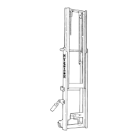
Hook Fork (Installation). Move the fork and carriage
so that the top hook on the fork can engage the upper car-
riage bar. Raise the carriage to move the lower hook
through the fork removal notch. Slide the fork on the
carriage so that both upper and lower hooks engage the
carriage. Engage the lock pin with a notch in the upper
carriage bar.
Pin Fork (Removal). Lower the carriage and put blocks
under a pin fork. When the weight of the forks have been
removed from the fork pin, remove the load backrest ex-
tension. The load backrest extension holds the fork pin
in the carriage. Slide the fork pin from its mount in the
carriage and through the eye of the fork. See
FIGURE 13. Use a lifting device to lift the fork away
from the carriage.
Pin Fork (Installation). Install the fork pin in the car-
riage. Align the eyes of the forks so that the forks will be
installed on the fork pin. When the fork pin is installed in
the carriage so that it holds the forks, install the load
backrest extension. Engage the fork with the lock pin.
Inspection Of Forks, Mast, and Lift Chains
(See FIGURE 14. and FIGURE 15.)
WARNING
Never work under a raised carriage or forks. Lower
the carriage or use blocks and chains on the mast
weldments and carriage so that they can not move.
Make sure the moving parts are attached to a part
that does not move.
Do not try to correct the alignment of the fork tips by
bending the forks or adding shims. Replace dam-
aged forks.
Never repair damaged forks by heating or welding.
Forks are made of special steel using special proce-
dures. Replace damaged forks.
1. FORK REMOVAL NOTCH
2. FORK
3. HOOK
1545
2
5
1
4
3
2
3
3
3
4
4. LOCK PIN ASSEMBLY
5. CARRIAGE
FIGURE 12. HOOK FORK