13
12565
1
2
3
4
5
5
1
1
2
2
3
3
4
2
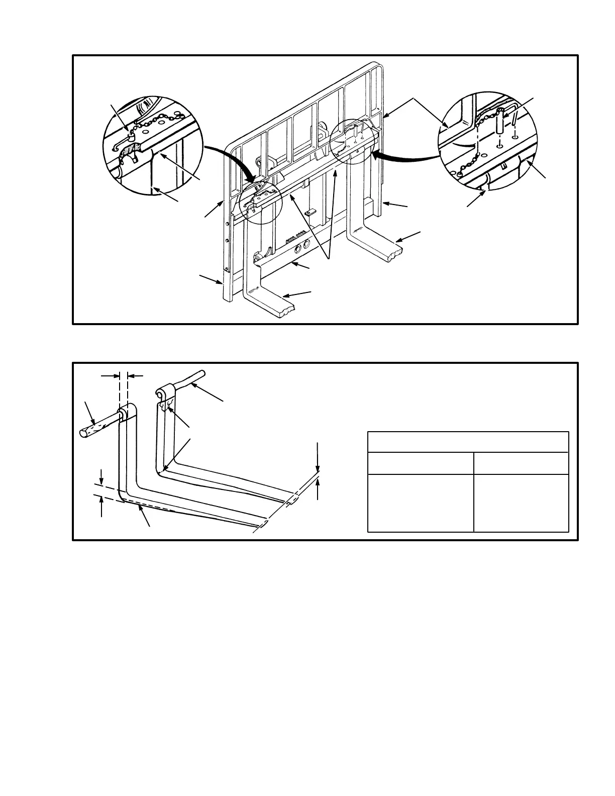
1. CARRIAGE
2. FORK
3. FORK PIN
4. LOCK PIN
5. LOAD BACKREST EXTENSION
FIGURE 13. PIN FORKS
3. FORK PIN DAMAGE
4. MUST BE 90% OF
DIMENSION X
5. FORK WEAR
1
5
3
3
2
11195
X
4
1. TIP ALIGNMENT
(MUST BE WITHIN 3%
OF FORK LENGTH)
2. CRACKS
FORK TIP ALIGNMENT
LENGTH OF FORKS 3% DIMENSION
915 mm (36 in) 27 mm (1.10 in)
1220 mm (48 in) 37 mm (1.45 in)
1830 mm (72 in) 55 mm (2.15 in)
FIGURE 14. CHECK THE FORKS
1. Inspect the welds on the mast and carriage for cracks.
Make sure that the capscrews and nuts are tight.
2. Inspect the channels for wear in the areas where the
rollers travel. Inspect the rollers for wear or damage.
3. Inspect the load backrest extension for cracks and
damage.
4. Inspect the forks for cracks and wear. Check that the
fork tips are aligned within 13 mm (0.5 in) of each other.
(See FIGURE 14.) Check that the bottom of the fork is
not worn (Item 5).
5. Replace any damaged or broken parts that are used to
keep the forks locked in position.
6. If the lift truck is equipped with a side–shift carriage
or attachment, inspect the parts for cracks and wear.
Make sure the parts that fasten the side–shift carriage or
attachment to the carriage are in good condition.
7. Check that the lift chains are correctly lubricated. Use
SAE 30 engine oil to lubricate the lift chains.
8. Inspect the lift chains for cracks or broken links and
pins. (See FIGURE 15.)