SCHEMATIC LOCATION NUMBER
The schematic is divided into rows with a letter
from A to J and into columns numbered 0 to 9 for
each sheet. See Figure 1.
The column numbering consists of the sheet num-
ber plus the column number. For example, column
57 is the 7th column on sheet 5.
The schematic location number is the combination
of a row letter and column number, which allows
quick identification of a point on the schematic. For
example, [57, A] is the 7th column on sheet 5, row
A.
ELECTRICAL COMPONENTS
Electrical components are indicated by a symbol
and a description that are placed close to each
other on the schematic. An example is the starter
relay on [38,C]. See Figure 1.
ELECTRICAL WIRES
Each electrical wire is indicated by a solid line and
has been identified with an identification number
and a color indication of the wire insulation. If a
wire continues on a different sheet, then the solid
line ends with an arrow and receives in addition
the schematic location number where this wire con-
tinues.
Wire Identification Number
Each electrical wire in the electrical schematic has
an identification number that is also printed on the
insulation of the wires.
The wire identification numbers consist of a func-
tion ID number and when needed a suffix letter.
The function ID numbers are numbered from 1
through 999. Specific ranges of numbers are as-
signed for different function ID groups. See Table 3.
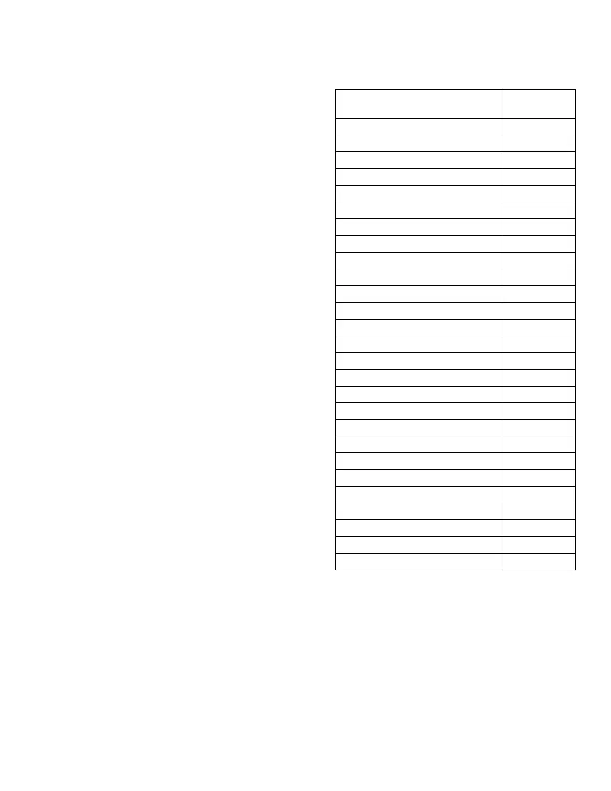
Table 3. Function ID Numbers
Function Group Number
Range
Grounds 101 - 149
Current sense ground 150 - 199
Switched B+ 200 - 239
Fused B+ 240 - 249
Regulated power 5V 250 - 279
Regulated power 12V 280 - 299
Analog inputs - hydraulics/mast 300 - 319
Analog inputs - chassis 320 - 339
Analog inputs - powertrain 340 - 399
Analog inputs - CAB/OHG 400 - 419
Additional analog inputs 420 - 499
Digital inputs - hydraulics/mast 500 - 509
Digital inputs - chassis 510 - 539
Digital inputs - powertrain 540 - 559
Digital inputs - CAB/OHG 560 - 569
Encoder inputs 570 - 599
Additional digital inputs 600 - 699
Digital outputs - hydraulics/mast 700 - 719
Digital outputs - chassis 720 - 749
Digital outputs - powertrain 750 - 779
Digital outputs - CAB/OHG 780 - 799
PWM outputs - hydraulics/mast 800 - 829
PWM outputs - chassis 830 - 839
PWM outputs - powertrain 840 - 889
PWM outputs - CAB/OHG 890 - 899
Communication (eg., CAN) 900 - 909
Non-standard functions 910 - 999
2200 SRM 1592 Electrical Schematic and System Description
3


 To Next Page