SPECIFICATIONS
• E24i™ Motor with Integrated Card
Requirements
Power Requirements
Power In•
24.0 VDC nominal @ 1.5 A maximumo
Normal operation from 22.0 – 28.0 VDC
Will allow operation above 28.0 VDC but control will get hotter.
Will allow operation below 22.0 VDC but full speed will be
unattainable.
29.0 + 0.2 VDC over-voltage detection (unit will cease normal o
operation)
19.0 + 0.2 VDC under-voltage detection (unit will cease normal o
operation)
Polarity protection is providedo
Note that the control’s ground does not attach to the metal
chassis; doing so assures a solid ground but then if the power
supply is reversed it’s positive output
Fuse non-replaceable 5 AMP. Fuse located under the cover.o
PNP Inputs•
PNP Input Signal Levelso
Active when pulled up above 18.0 VDC
Need to be able to source 3 mA
Two input signalso
Motor Run
Motor Reverse
Analog Speed Input•
Allow the speed to be controlled from a single point
Voltage range: 0-10 VDC
Minimum impedence presented to input: 5K
PNP Output•
Signal Levelso
Sources current when active
Maximum current for this unprotected output is 50mA.
A150ΩseriesresistorhelpsthePNPoutputlimitcurrentdraw
for most situations; voltage out is thus lower as current draw
increases.
Voltage dependent on input power and current draw.
One output signalo
Motor Running
Environmental Requirements
Temperature•
The unit shall operate within specified limits over the range of -20 to o
40 °C (-4 to 120 °F).
The unit can be stored in the range of -40 to 85 °C (-40 to 185 °F).o
Humidity•
The unit shall operate within specified limits in relative humidity in the o
range of 20 to 90% (non-condensing).
The unit can be stored in the range of 5 to 95% (non-condensing).o
Safety – Unintended Use Considerations
Installer•
This product is intended for installation by qualified personnel only; o
although of relatively low voltage there are dangerous levels of current
controlled on the board that are not protected from misplaced fingers.
Note that the cover makes it difficult to touch any power.
A tool will be required to move the DIP switches; a plastic-tip
screwdriver is recommended.
User•
Product shall be located away from the user such that touching of the o
control is not possible.
MAINTENANCE
• EZLogic
®
System
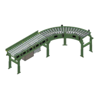
EZLogic® Accumulation System Connections
The Model 190-E24EZ is equipped with the EZLogic® Accumulation System. The
following basic information may be used as a guide during the installation and
initial setup of the conveyor. For detailed information about EZLogic® system
components, options, functions, and programming, please refer to the EZLogic®
GEN3 Component Manual.
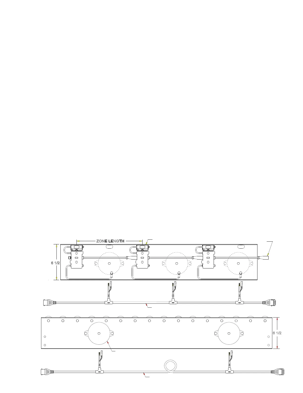
Each EZLogic® zone controller is equipped with sealed connectors for zone-to-
zone communication, solenoid output, and zone stop connections (Figure 7A).
These connections are described in the following sections.
ZONE CONNECTIONS
Each zone has a cordset terminated with a female micro-connector and a male
micro-connector. This cordset provides power to all the controllers on the conveyor
as well as communication between controllers. All controllers are mounted and
connected at the factory within each conveyor section. Connections between
sections are made at installation. (See Conveyor Set-Up, page 4). The cordset
from one controller is always connected to the cordset on the upstream side of it.
This is the way the controllers know which direction product is flowing. The cordset
on the infeed end of the conveyor is simply bundled and tied in the accumulation
channel and is not connected. The infeed cordset may be replaced with an infeed
zone terminator (P/N 032.550). Protective caps are provided to seal unused
connectors.
An optional conveyor-to-conveyor connector is required when two conveyors are
joined end-to-end. Please refer to the EZLogic® GEN3 Component Manual for
more information.
6 1/2
ZONE LENGTH
Zone Controller
Cordset
Wiring Harness W/Drops
Wiring Harness W/Drops
6 1/2
Unidrive Motor
Figure 6B
• E24 Connections
Figure 6A
• E24EZ Connections
6