reach the full speed. This is not a cause for concern and no corrective action
is required.
Fault Indicator LED (Red)
This LED is off under normal circumstance. If a problem is detected, it provides
one of the following signals:
One (1) flash in 4 seconds:• The motor has a hardware problem. Return it
to your supplier.
Two (2) flashes in 4 seconds:• The input voltage is too low. Increase the
voltage.
Three (3) flashes in 4 seconds:• The input voltage is too low.
Increase the voltage.
Four (4) flashes in 4 seconds:• There is a problem with the motor
or commutation sensors.
Five (5) flashes in 4 seconds:• Control over temperature.
Six (6) flashes in seconds:• Extreme over current.
Constantly ON:• The motor is stalled or the sensor is continuously
blocked. Check for mechanical obstructions.
Blown Fuse Indicator LED (Red)
This LED will be illuminated if the 5.0 amp internal fuse is blown and
power is applied with the proper polarity. If the blown fuse LED is
illuminated, return the motor to your Integration Partner or supplier for
analysis or repair. The 5.0 amp fuse is not user-accessible.
Setup Selection Switches
There are six dipswitches on the control board that are used to configure the board
for specific applications. The switches are numbered 1 through 6, with 1 being the
top switch when viewing the motor as shown in the figure. Switch 1 and 2 are read
only at power-up, meaning that any changes to switches will not take effect until
the power is cycled to the E24™ system. Switches 3-6 are read dynamically. The
functions of the switches are as follows:
Switch 1 - Motor Rotation Selector Switch
This switch determines the default or “forward” direction of rotation of the E24™
motor. When the switch is in the “ON” (right) position the motor rotates clockwise
when viewed from the back of the motor. When the switch is in the “OFF” (left)
position the motor rotates counter-clockwise when viewed from the back of the
motor.
Switch 2 - Dynamic Braking Enable Switch
This switch is used to enable the dynamic braking feature. When the switch is in
the “OFF” (left) position the dynamic braking feature acts to stop motor rotation
quickly when the motor is turned off. When the switch is in the “ON” (right) position
the motor will coast to a stop when it is turned off.
Switches 3 through 6 - Speed Control Switches
These switches determine the operating speed, making it simple to match speeds
in multiple zones. The speed switches are read dynamically allowing the user to
change speeds while powered up.
RPM
Out
Speed, FPM DIP SWITCH SETTINGS
STD
SPOOL
SPEED UP
SPOOL
SW3 SW4 SW5 SW6
350 174 254 OFF OFF OFF OFF
330 164 240 ON OFF OFF OFF
310 154 225 OFF ON OFF OFF
290 144 211 ON ON OFF OFF
270 134 196 OFF OFF ON OFF
250 124 182 ON OFF ON OFF
230 114 167 OFF ON ON OFF
210 104 153 ON ON ON OFF
190 95 138 OFF OFF OFF ON
170 85 123 ON OFF OFF ON
150 75 109 OFF ON OFF ON
130 65 94 ON ON OFF ON
110 55 80 OFF OFF ON ON
90 45 65 ON OFF ON ON
70 32 51 OFF ON ON ON
50 25 36 ON ON ON ON
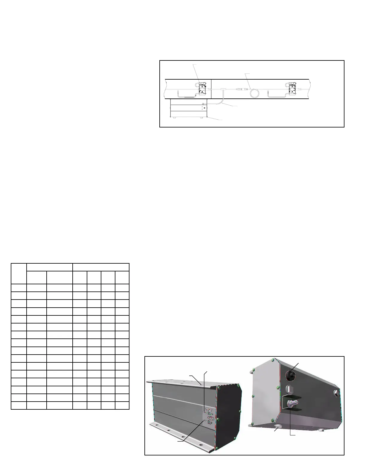
• IOP Unit (Power Suppy for GEN3 EZLogic®)
The model 190-E24EZ is equipped with an IOP unit (power supply.) The IOP
unit provides DC power for the EZLogic® system and provides a wiring hub for
advanced features (if I/O boards are present). The IOP unit connects to the
EZLogic® system by way of an IOP Tee Cable mounted in line with the zone
controller cordsets (see Figure 9A).
Note: See EZLogic® GEN3 Component Manual and IOP Solutions Manual for
more information.
• Power Supply Unit for Motor
The E24™ family of conveyors is equipped with a 24 volt DC power suppy unit
for providing power to the drive card and motor combination. Each power supply
provided is a high efficiency DC power supply in a sealed industrial enclosure.
(Figure 10A)
The various wiring connections, adjustments and settings, and electrical
specifications of the power supply unit are described in this section.
Electrical Connections
Input power connections are made inside the enclosure. Wiring harness power
connections are made to connector on the outside of the enclosure.
AC Input
AC power for the power supply unit is connected directly to the disconnect switch,
and the ground wire is connected to the grounding terminal block. (Figure 10B and
10C)
The dual voltage single phase input powered units will automatically adjust to the
115 VAC or the 230 VAC input power.
DC Output
Connect the wiring harness to a connector on the side of the enclosure.
NOTE: Based on standard O-rings used, no more than 20 cards and motors
can be connected to one side of a power supply unit. When more than 20
amps is required, you must use a 40 amp power supply unit and make sure
that no more than 20 amps is required from each side of the power supply
unit.
Mount the power supply unit near the center of the conveyors and connect the
wiring harnesses to each side of the power supply.
A gender changer cable is supplied for one side of the power supply.
Main Power Disconnect Switch
The main power disconnect switch handle is located on the front door. The switch
can be used to turn the conveyor on and off to perform maintenance. It may be
“locked out” in the off position if desired/required.
EZLOGIC® ZONE CONTROLLER CORDSET
EZLOGIC® ZONE CONTROLLER
IOP TEE CABLE
IOP
(CABLES DEL CONTROLADOR DE ZONA DEL EZLOGIC®)
(CONTROLADOR DE ZONA DEL EZLOGIC®)
(CABLE TEE DEL IOP)
(IOP)
FIGURE 9A
Output Power Receptacle
On/Off Switch
Conduit Plugs
AC Power
Indicator Light
DC Power
Indicator Light
Mounting Holes
FIGURE 9B
8